
LED lamp

An LED lamp and housing technology, applied in the field of lighting, can solve the problems of people stepping on, scratches on hard objects, damage to the insulation of the power supply line, and easy induction of electric shock accidents, so as to prevent accidental electric shock accidents, reduce waste of mains power, and improve The effect of power supply security and service life

Active Publication Date: 2017-06-27
ZHEJIANG MINGCHUANG OPTO ELECTRONICS TECHNOLOGH
View PDF4 Cites 0 Cited by
  • Summary
  • Abstract
  • Description
  • Claims
  • Application Information

AI Technical Summary

Problems solved by technology

[0002] In the actual construction of the construction site, due to the tight schedule or construction needs, construction needs to be carried out at night, so the lighting on the construction site has become an indispensable tool in the construction process. However, due to the long power supply connection required in the construction lighting process , making it extremely difficult to take in and out the wires, increasing the workload and reducing work efficiency. At the same time, when not in use, the power supply wires are exposed to the outside world for a long time and are vulnerable to various accidental damages, such as people trampled on, hard objects scratches, etc., resulting in power supply failures. The insulation skin on the outside of the line is damaged, and it is easy to induce electric shock accidents if it is not found in time. In addition, the existing LED lights for construction work through connection with the mains, resulting in waste of power resources. There are major drawbacks and need to be improved.

Method used


Image

  • LED lamp
  • LED lamp
  • LED lamp

Examples


Embodiment Construction

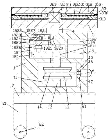
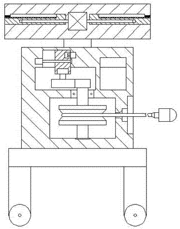
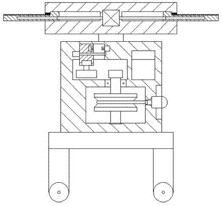
[0022] Such as Figure 1-Figure 4 As shown, an LED lamp of the present invention includes a housing 1 fixed on the top of the machine base 2 and a ceiling 3 arranged above the housing 1. A cavity 11 is provided in the housing 1, and the cavity The housing 1 at the top of the cavity 11 is provided with a first transverse cavity 18 and a second transverse cavity 19, the inner top wall of the first transverse cavity 18 is provided with a sliding groove 182, and the cavity 11 on the right side The outer wall of the housing 1 is provided with a pick-and-place slot 17, and a passage slot 15 and an engaging slot 16 are provided between the pick-and-place slot 17 and the cavity 11, and the cavity 11 is provided with a vertically extending The revolving pin shaft 12, the top extension section of the revolving pin shaft 12 passes through the inner wall of the housing 1 and enters the first transverse cavity 18, the tail end of the revolving pin shaft 12 in the first transverse cavity 18...


PUM


Abstract

The invention discloses an LED lamp. The LED lamp comprises a shell fixed to the top of a machine seat and a ceiling arranged above the shell. A cavity is formed in the shell. A first transverse cavity and a second transverse cavity are formed in the portion, on the top of the cavity, in the shell. A sliding groove is formed in the top wall in the first transverse cavity. A taking and placing groove is formed in the portion, on the right side of the cavity, on the outer wall of the shell. A penetrating groove and a clamping groove are formed between the taking and placing groove and the cavity. A rotary pin shaft is arranged in the cavity in a vertically-extending manner. The extending section of the top of the rotary pin shaft penetrates the inner wall of the shell and enters the first transverse cavity. A first tooth-shaped wheel is fixedly arranged at the tail end of the rotary pin shaft in the first transverse cavity. A rolling disc is fixedly arranged on the portion, in the cavity, of the rotary pin shaft. A power line is wound around the inner portion of the rolling disc. A sliding block is arranged in the sliding groove. The bottom of the sliding block enters the first transverse cavity. A first electromotor is arranged in the end face of the bottom of the sliding block. The LED lamp is simple in structure, convenient to operate, capable of conducting the take-up work and high in safety.

Description

technical field [0001] The invention relates to the technical field of lighting, in particular to an LED lamp for building construction. Background technique [0002] In the actual construction of the construction site, due to the tight schedule or construction needs, construction needs to be carried out at night, so the lighting on the construction site has become an indispensable tool in the construction process. However, due to the long power supply connection required in the construction lighting process , making it extremely difficult to take in and out the wires, increasing the workload and reducing work efficiency. At the same time, when not in use, the power supply wires are exposed to the outside world for a long time and are vulnerable to various accidental damages, such as people trampled on, hard objects scratches, etc., resulting in power supply failures. The insulation skin on the outside of the line is damaged, and it is easy to induce electric shock accidents...

Claims


Application Information

Patent Timeline
IPC IPC(8): F21S9/03F21V23/00F21V23/06F21Y115/10
CPCY02B10/10F21S9/032F21V23/002F21V23/06
Inventor 范翠贞
Owner ZHEJIANG MINGCHUANG OPTO ELECTRONICS TECHNOLOGH
Learn More