Novel cutting fixture

A fixture, a new type of technology, applied in the direction of turning equipment, manufacturing tools, tool holder accessories, etc., can solve the problems of low clamping efficiency, troublesome clamping, high labor intensity of workers, etc., to ensure clamping accuracy and increase clamping speed and efficiency, easy to disassemble the effect of the workpiece

Pending Publication Date: 2021-03-30
GUANGZHOU CITY POLYTECHNIC
View PDF0 Cites 4 Cited by
  • Summary
  • Abstract
  • Description
  • Claims
  • Application Information

AI Technical Summary

Problems solved by technology

However, although the clamping force and clamping accuracy can be kept low when the chuck is positioned, its clamping is cumbersome, the clamping efficiency is low, and the labor intensity of the workers is high; Clamping speed and efficiency, but the clamping accuracy cannot be guaranteed

Method used


Image

  • Novel cutting fixture
  • Novel cutting fixture
  • Novel cutting fixture

Examples


Embodiment Construction

[0019] The specific implementation manners of the present invention will be further described in detail below in conjunction with the accompanying drawings and embodiments. The following examples are used to illustrate the present invention, but are not intended to limit the scope of the present invention.

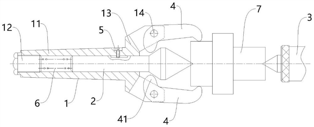
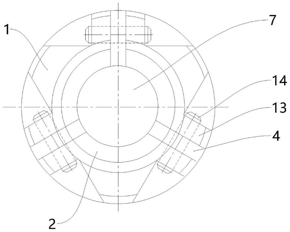
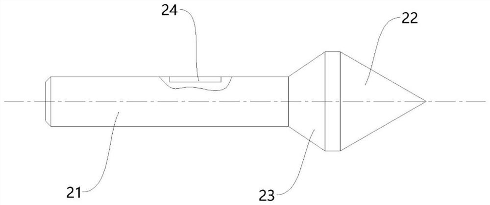
[0020] A preferred embodiment of a novel cutting fixture of the present invention, such as Figure 1 to Figure 3 As shown, the new cutting fixture includes a fixture body 1, a centering center 2 and a live center 3, the centering center 2 and the live center 3 are coaxially arranged, and the centering center 2 and the live center 3 are respectively used to abut against the workpiece 7. At both ends in the axial direction, the clamp body 1 is used for clamping in the taper hole of the spindle of the lathe.

[0021] The clamp body 1 includes a main body 11 and a torque adjusting screw 12 threadedly mounted on the tail end of the main body 11. The main body 11 is a hollow st...


PUM


Abstract

The invention relates to the technical field of machining, and discloses a novel cutting fixture. The fixture comprises a fixture body, a centering centre and a live centre; the centering centre and the live centre are coaxially arranged; the centering centre is axially and movably inserted into the fixture body; an elastic piece for elastically supporting the centering centre is arranged at the tail end of the fixture body; a clamping jaw is further rotationally assembled on the fixture body; the front end of the clamping jaw is defined as a clamping end, and the tail end is defined as a driving end; a cam is formed at the driving end; the centering centre is provided with a jacking slope for jacking the cam during axial movement; the clamping jaw is provided with a clamping position forenabling the jacking inclined surface to jack the cam to enable the clamping end to clamp the workpiece and a releasing position for enabling the jacking inclined surface to be separated from the camto enable the clamping end to release the workpiece in the rotating stroke. When the workpiece is machined, the jacking inclined surface of the centering centre jacks the cam, the clamping end of theclamping jaw clamps the workpiece in the radial direction, the larger the movement amount of the centering centre is, the larger the clamping force of the clamping jaw is, clamping is completed whilethe clamping force is guaranteed, the clamping speed and efficiency are improved, and meanwhile, the clamping precision is guaranteed.

Description

technical field [0001] The invention relates to the technical field of machining, in particular to a novel cutting fixture. Background technique [0002] In the process of cutting, shaft parts are often encountered processing parts. When processing shaft parts, they must be correctly positioned and clamped in the machine tool fixture, such as ensuring coaxiality and positioning accuracy. Keep it in the correct position throughout the cutting process, so as to ensure the processing quality of the parts. [0003] At present, there are many clamping methods in the machining of parts. The common method is to use a chuck to clamp the end of the shaft part, and use a live center to press the other end of the shaft part to position the shaft part. However, although the clamping force and clamping accuracy can be kept low when the chuck is positioned, its clamping is cumbersome, the clamping efficiency is low, and the labor intensity of the workers is high; Clamping speed and effi...

Claims


Application Information

Patent Timeline
Patent Type & Authority Applications(China)
IPC IPC(8): B23B23/04B23B31/103
CPCB23B23/04B23B31/103
Inventor 李庆荣李国东
Owner GUANGZHOU CITY POLYTECHNIC
Why Eureka
Try Eureka