
Assembling device of transformer low-voltage outgoing line structure

A low-voltage outgoing line and assembly device technology, which is applied in the direction of transformer/inductor coil/winding/connection, transformer/inductor parts, prevention/reduction of unnecessary electric/magnetic influence, etc., can solve the loss of magnetic force line and increase the transformer Problems such as load loss, to achieve the effect of maintaining normal and stable work and avoiding load loss

Active Publication Date: 2021-03-26
GUANGDONG POWER GRID CO LTD +1
View PDF10 Cites 0 Cited by
  • Summary
  • Abstract
  • Description
  • Claims
  • Application Information

AI Technical Summary

Problems solved by technology

[0005] The purpose of the present invention is to provide an assembly device for a transformer low-voltage outgoing line structure, so as to solve the problem of drawing out a linear array of outgoing line posts whose adjacent spacing is too small in the limited space where the coil windings on the low-voltage side of the prior art are located, causing the magnetic force line to pass through the channel steel. Loss is generated, which increases the technical problem of transformer load loss

Method used


Image

  • Assembling device of transformer low-voltage outgoing line structure
  • Assembling device of transformer low-voltage outgoing line structure
  • Assembling device of transformer low-voltage outgoing line structure

Examples


Embodiment Construction

[0029] In order to make the purpose, features and advantages of the present invention more obvious and understandable, the technical solutions in the embodiments of the present invention will be clearly and completely described below in conjunction with the accompanying drawings in the embodiments of the present invention. Obviously, the following The described embodiments are only some, not all, embodiments of the present invention. Based on the embodiments of the present invention, all other embodiments obtained by persons of ordinary skill in the art without making creative efforts belong to the protection scope of the present invention.

[0030] The technical solutions of the present invention will be further described below in conjunction with the accompanying drawings and through specific implementation methods.

[0031] In the description of the present invention, it should be understood that the orientations or positional relationships indicated by the terms "upper", "...


PUM


Abstract

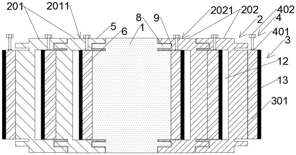
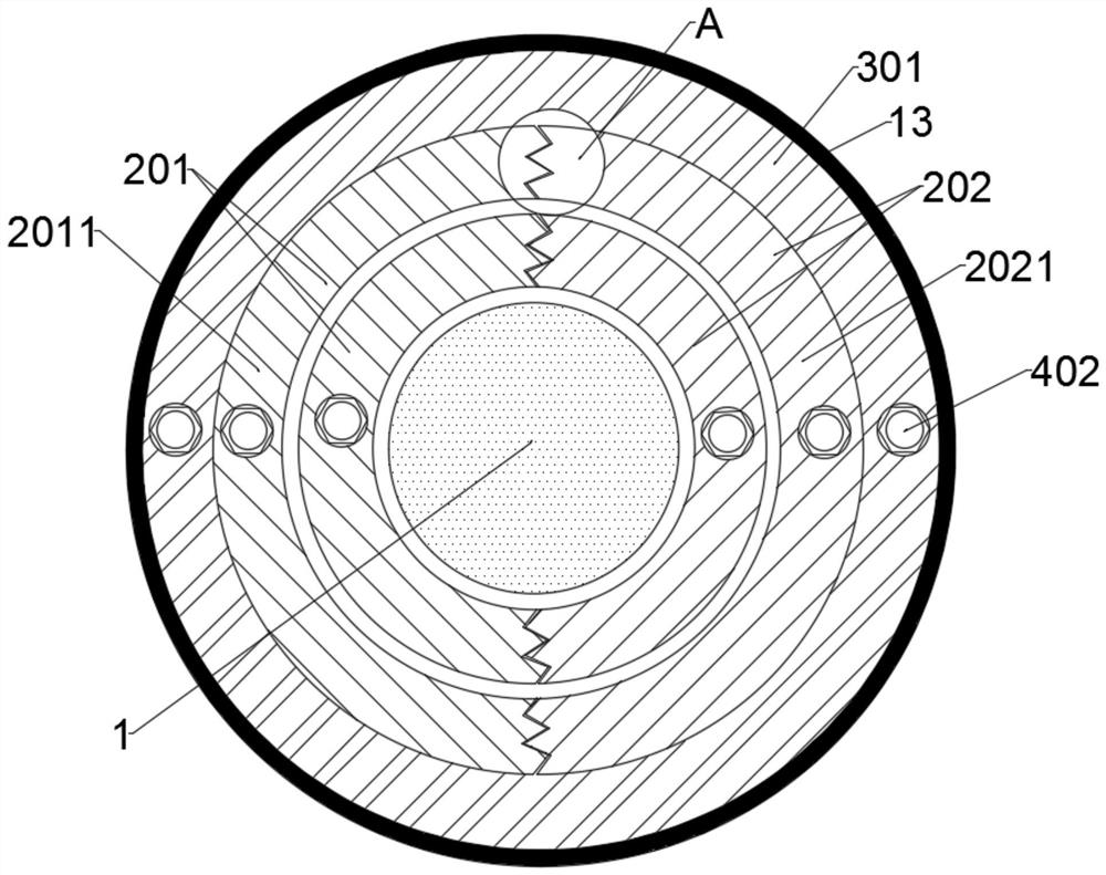
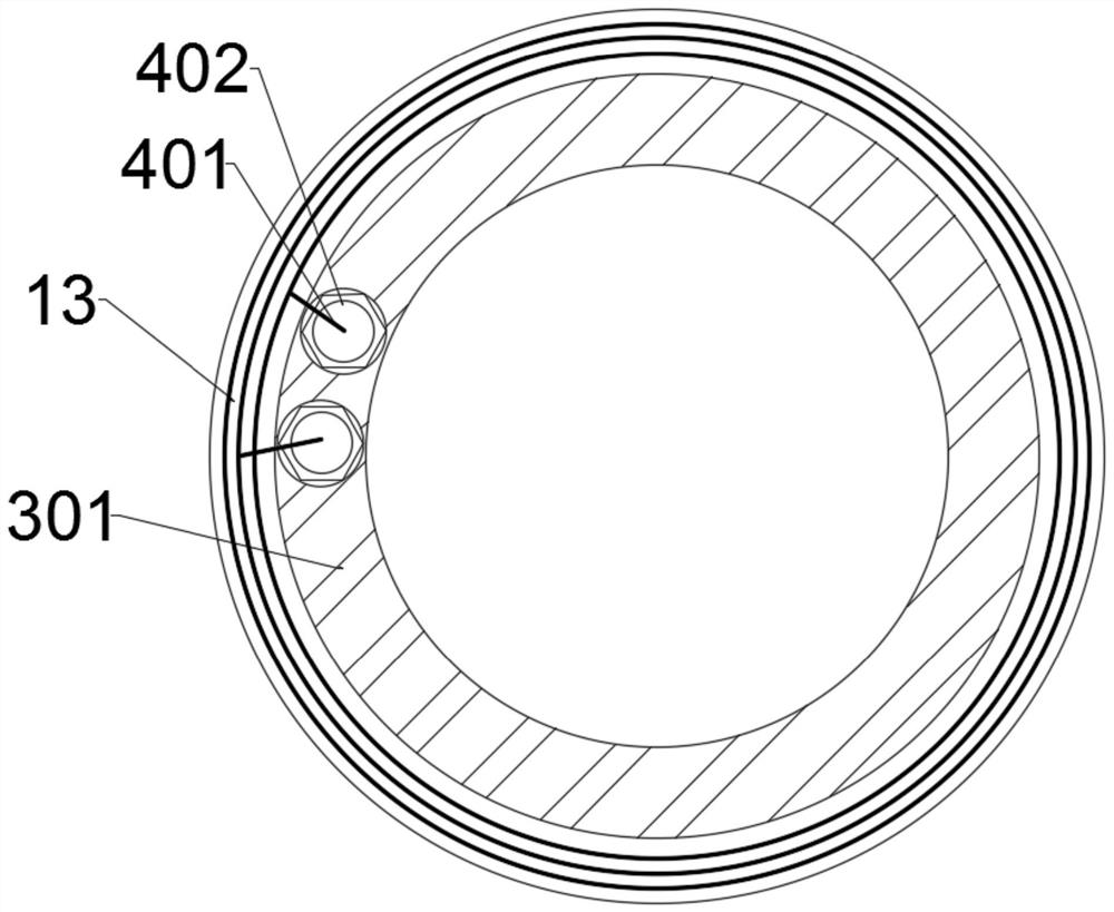
The invention discloses an assembling device of a transformer low-voltage outgoing line structure. The assembling device comprises a transformer framework, a winding fixing structure and a low-voltagecoil winding are arranged on the periphery of the transformer framework, and the low-voltage coil winding comprises a plurality of low-voltage side coils. The low-voltage coil winding electrically connects a plurality of low-voltage side coils according to transformation requirements so as to obtain the number of turns of the low-voltage side coils in various number combinations, and a low-voltage wire outlet structure is reserved and used for being electrically connected with an external electric appliance and outputting power supply voltage to the external electric appliance. The winding fixing structure is used for sequentially stacking, nesting and fixing a plurality of low-voltage side coils in the low-voltage coil winding to the periphery of a transformer framework. The magnetic field of the current flowing to the external electric appliance through the external copper cylinder at the channel steel at the top of the transformer is weak, no loss or tiny loss is generated when themagnetic line of force passes through the channel steel, and the transformer is effectively prevented from generating extra load loss.

Description

technical field [0001] The invention relates to the technical field of power transformation, in particular to an assembly device for a transformer low-voltage outlet structure. Background technique [0002] A transformer is a power device that uses the principle of electromagnetic induction to change the AC voltage. It can play the role of voltage conversion, current conversion, impedance conversion, and voltage stabilization in the circuit. It is widely used in many fields such as power supply, machinery manufacturing, metallurgy, and railways. ; [0003] With the increasing use of transformers, people have higher and higher requirements for the use of transformers. They are no longer satisfied with transformers with fixed transformer specifications. They hope to obtain different transformer combinations on the same transformer. The current commonly used method is The high-voltage side or low-voltage side windings are used to lead out multiple externally connected outgoing...

Claims


Application Information

Patent Timeline
Patent Type & Authority Applications(China)
IPC IPC(8): H01F27/28H01F27/29H01F27/30H01F27/32H01F27/34
CPCH01F27/28H01F27/29H01F27/306H01F27/325H01F27/34
Inventor 钱强张汉光李伟波赵光宇
Owner GUANGDONG POWER GRID CO LTD
Learn More