
Tunnel deformation real-time monitoring method and device

A technology of real-time monitoring and tunneling, applied in the direction of measuring devices, optical devices, instruments, etc., can solve the problems of non-real-time detection, long detection cycle, inability to effectively warn, etc., and achieve the effect of intensive monitoring points

Active Publication Date: 2021-03-26
NANJING PIONEER AWARENESS INFORMATION TECH CO LTD
View PDF6 Cites 4 Cited by
  • Summary
  • Abstract
  • Description
  • Claims
  • Application Information

AI Technical Summary

Problems solved by technology

During tunnel excavation, it is necessary to manually install multiple reflective prisms (usually 3 to 7) at fixed intervals on the top of the tunnel. The installation of reflective prisms is inconvenient and poses certain construction safety hazards
During inspection, it is necessary to stop construction and use a total station for manual monitoring. The interval between each inspection is generally 2 to 4 hours. This inspection method is time-consuming and laborious, and delays the construction progress.
[0004] In addition, the above-mentioned current total station monitoring method can only monitor 3 to 7 points in each section of the tunnel, which is very sparse, and the time interval for monitoring deformation is relatively long. If a disaster accident occurs during the monitoring window period, it will not be able to effectively warn
[0005] For operational tunnels, motion detection vehicles are usually used to deploy structured light sources and image sensors on the detection vehicles, but this detection method cannot be used in tunnels under construction that use blasting methods, and the detection period is long and non-real-time detection

Method used


Image

  • Tunnel deformation real-time monitoring method and device
  • Tunnel deformation real-time monitoring method and device
  • Tunnel deformation real-time monitoring method and device

Examples


Embodiment Construction

[0031] The technical solution of the present invention will be explained more clearly and completely through the description of preferred embodiments of the present invention in conjunction with the accompanying drawings.

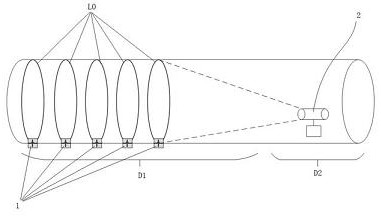
[0032] Such as figure 1 As shown, the tunnel deformation real-time monitoring device of the preferred embodiment of the present invention includes a plurality of structured light sources 1 and a monitoring terminal 2 .

[0033] A plurality of structured light sources 1 are erected on the face of the tunnel and the initial support area to be monitored, and these areas are collectively referred to as the monitoring area or the unstable area D1. Preferably, a plurality of structured light sources 1 are arranged at equal intervals. The structured light source 1 is a multi-band light source. At the same time, the monitoring terminal 2 has a multi-band light source sensing function, and the measurement results of the multi-band light source are comprehensively a...


PUM


Abstract

The invention discloses a tunnel deformation real-time monitoring method and a device, and the method comprises the steps: S1, erecting a plurality of structured light sources in an unstable region ofa tunnel structure which needs to be monitored, erecting a monitoring terminal in a relatively stable region of the tunnel structure, and enabling the monitoring terminal to communicate with the plurality of structured light sources; S2, adopting the monitoring terminal to observe all structured light in an unstable area of the tunnel structure and obtain a structured light curve in real time; and S3, adopting a data processing unit to analyze the structured light imaging change, detect the tunnel deformation degree and offset distance in real time, and monitor tunnel single-section settlement, convergence, multi-section overall settlement and other diseases. The method is suitable for tunnels under construction and operating tunnels, monitoring points are dense, and tunnel deformation can be monitored in real time.

Description

technical field [0001] The invention relates to the field of deformation monitoring of tunnel structures, in particular to a method and device for real-time monitoring of tunnel deformation. Background technique [0002] The excavation methods of tunnels under construction mainly include blasting and shield tunneling. The shield method is mainly used in the construction of subway tunnels. The cutterhead excavation, slag transportation, pipe patching, and track laying are carried out at the same time. The structure is relatively stable and the cost is high. The blasting method is mainly used in the construction of high-speed railway tunnels. First, blasting is carried out on the tunnel face. After the blasting, I-beams are erected and cement is poured to form the primary support area. The deformation rate in the primary branch area is relatively high, and disasters such as tunnel settlement and convergence are extremely prone to occur, so real-time monitoring of deformation ...

Claims


Application Information

Patent Timeline
Patent Type & Authority Applications(China)
IPC IPC(8): G01B11/16
CPCG01B11/16G01M5/0041G01M5/0025G01M5/0091E21F17/18G06T7/11G06T7/13G06T7/248G06T7/0002G06T2207/20021G06T2207/30184H04N7/181
Inventor 石峥映王列伟朱明连捷黄友群陆海东李阳刘洋李沛遥吴国强夏宝前
Owner NANJING PIONEER AWARENESS INFORMATION TECH CO LTD
Learn More