
Arch-first and beam-second construction method for bracket-free tied arch

A technology of arch first and beam later and construction method, which is applied in the direction of erection/assembly of bridges, bridges, bridge construction, etc., and can solve the problem of limited bearing capacity of steel pipe rods of full hall brackets, high requirements for foundation bearing capacity, and high requirements for pouring quality control measures, etc. problems, to achieve the effect of meeting the structural installation quality, ensuring the navigation requirements, widely promoting the application value and reference significance

Inactive Publication Date: 2021-03-26
浙江省建投交通基础建设集团有限公司
View PDF5 Cites 3 Cited by
  • Summary
  • Abstract
  • Description
  • Claims
  • Application Information

AI Technical Summary

Problems solved by technology

[0002] The traditional support method construction starts from the ground and builds the steel pipe support to the vault, and then carries out formwork, pouring, maintenance and other constructions. The biggest advantage of this method is that it does not require large-scale hoisting equipment, and its disadvantage is the consumption of support formwork for construction. Large, long construction period, large investment of manpower, steel pipe support erection requires high bearing capacity of the foundation, and the bearing capacity of the steel pipe rod of the conventional full hall support is limited, and the safety risk is relatively large. For large-volume concrete structures, pouring in sections and blocks There are many, high requirements for pouring quality control measures, navigation requirements for waterways, and great limitations in the construction of bridges and high piers in mountainous areas

Method used


Image

  • Arch-first and beam-second construction method for bracket-free tied arch
  • Arch-first and beam-second construction method for bracket-free tied arch
  • Arch-first and beam-second construction method for bracket-free tied arch

Examples


Embodiment Construction

[0030] In order to make the object, technical solution and advantages of the present invention clearer, the present invention will be further described in detail below in conjunction with the accompanying drawings and embodiments. It should be understood that the specific embodiments described here are only used to explain the present invention, not to limit the present invention.

[0031] On the contrary, the invention covers any alternatives, modifications, equivalent methods and schemes within the spirit and scope of the invention as defined by the claims. Further, in order to make the public have a better understanding of the present invention, some specific details are described in detail in the detailed description of the present invention below. The present invention can be fully understood by those skilled in the art without the description of these detailed parts.

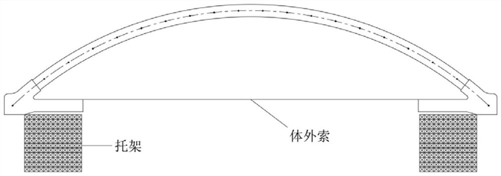
[0032] Such as Figure 1-3 As shown, a kind of construction method of tie-bar arch without support, a...


PUM


Abstract

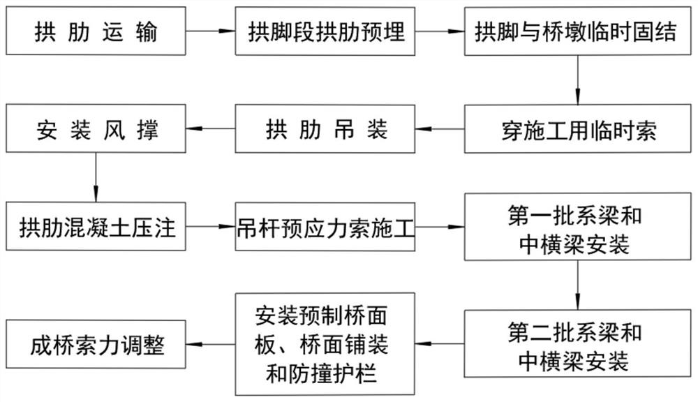
The invention discloses an arch-first and beam-second construction method for a bracket-free tied arch, and belongs to the technical field of building construction. The method comprises the followingsteps: 1, transporting arch ribs; 2, pre-burying arch ribs of arch foot sections; 3, temporarily solidifying the arch feet and the bridge piers; 4, penetrating a temporary cable for construction: pulling the temporary cable to the cross beam at the mounting end, fixing the temporary cable through an anchorage device, and circularly constructing and penetrating the cable until the end; 5, hoistingarch ribs; 6, mounting a wind brace; 7, performing pressure injection on arch rib concrete; 8, performing suspender prestressed cable construction; 9, mounting a tie beam and a middle cross beam; 10,installing prefabricated bridge decks, bridge deck pavement and anti-collision guardrails; and 11, adjusting the cable force of the finished bridge suspender. By the adoption of the construction method, the construction period is shortened, and the labor intensity of workers is reduced; and the navigation requirement is guaranteed during construction, the balance of stress changes in arch structure construction is effectively guaranteed, the safety of bridge construction and later operation is guaranteed, the ecological environment is protected, and wide application and popularization value and reference significance are achieved.

Description

technical field [0001] The invention belongs to the technical field of building construction, and in particular relates to a construction method of a bracketless tie rod arch first arch and then beam. Background technique [0002] The traditional support method construction starts from the ground and builds the steel pipe support to the vault, and then carries out formwork, pouring, maintenance and other constructions. The biggest advantage of this method is that it does not require large-scale hoisting equipment, and its disadvantage is the consumption of support formwork for construction. Large, long construction period, large investment of manpower, steel pipe support erection requires high bearing capacity of the foundation, and the bearing capacity of the steel pipe rod of the conventional full hall support is limited, and the safety risk is relatively large. For large-volume concrete structures, pouring in sections and blocks There are many, high requirements for pouri...

Claims


Application Information

Patent Timeline
Patent Type & Authority Applications(China)
IPC IPC(8): E01D21/00
CPCE01D21/00
Inventor 严伟飞陈国宝袁野章贝贝黄东沈国伟林京京高钧健
Owner 浙江省建投交通基础建设集团有限公司
Learn More