
Tamping machine for building construction

A technology of building construction and tamping machine, which is used in construction, road, road repair and other directions

Active Publication Date: 2021-03-26
中铁十四局集团青岛工程建设有限公司
View PDF9 Cites 0 Cited by
  • Summary
  • Abstract
  • Description
  • Claims
  • Application Information

AI Technical Summary

Problems solved by technology

[0004] The purpose of the present invention is to solve the problem that the existing ramming machine needs the cooperation of many people to use it, and proposes a ramming machine for building construction

Method used


Image

  • Tamping machine for building construction
  • Tamping machine for building construction
  • Tamping machine for building construction

Examples


Embodiment 1

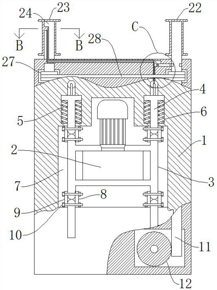
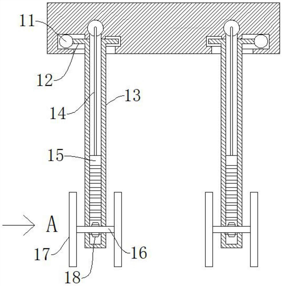
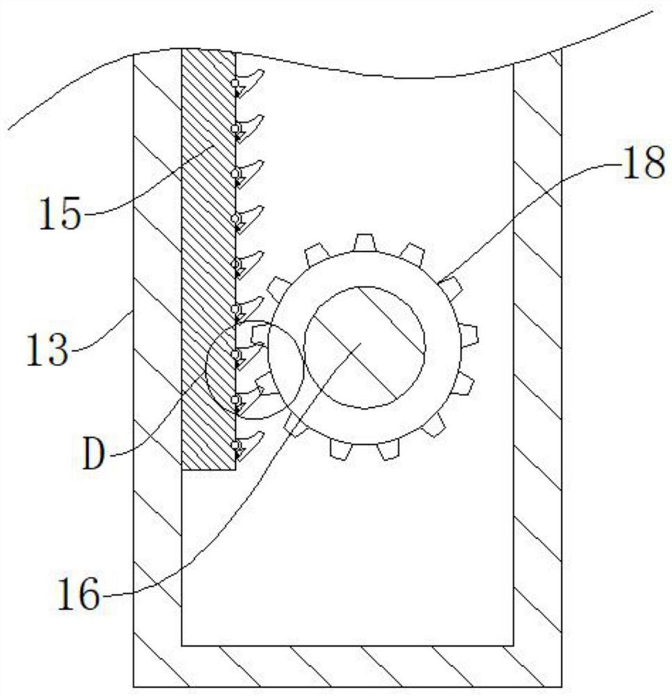
[0034] refer to Figure 1-8 , a kind of tamping machine for construction, comprising a mobile workbench 1, a ramming body 2, a through groove 7 is arranged in the mobile workbench 1, a fixed frame 3 is connected in the through groove 7, and the tamping body 2 is fixedly connected to a fixed In the frame 3, a first support leg 13 is symmetrically connected to one side of the lower end of the mobile workbench 1, and a second support leg 34 is fixedly connected to the side far away from the first support leg 13 at the lower end of the mobile workbench 1. The lower ends of the two support legs 34 are all rotatably connected with a rotating wheel 17 .

[0035] When using the device, at first the device is moved to the place of use, in order to move the device to the place of use conveniently, the first guard 22 and the second guard 23 can be held to push the device, because the first supporting legs 13, The lower ends of the second supporting legs 34 are all connected with the rot...

Embodiment 2

[0041] refer to figure 1 , Figure 7 , a kind of tamping machine for building construction, which is basically the same as that of Embodiment 1, and furthermore, a plurality of sets of sliding grooves 6 are arranged in the mobile workbench 1, sliding plates 4 are slidably connected in the sliding grooves 6, and sliding plates 4 are slidably connected in the sliding grooves 6. The first thrust spring 5 is symmetrically connected, and the two ends of the first thrust spring 5 are fixedly connected with the sliding groove 6 and the mobile worktable 1 respectively, and the sliding plate 4 is connected with the fixed frame 3, so as to absorb the vibration generated by the tamping body 2 .

Embodiment 3

[0043] refer to figure 1 , a ramming machine for building construction, which is basically the same as Embodiment 1, and furthermore: includes fastening bolts 10, and the two sides of the fixed frame 3 are respectively connected with a first fixed plate 8, a second fixed plate 9, the first fixed plate One side of the fixed plate 8 and the second fixed plate 9 away from the fixed frame 3 is connected with the sliding plate 4, and the first fixed plate 8 and the second fixed plate 9 are connected with the sliding plate 4 and the fixed frame 3 by fastening bolts 10, One end of the fastening bolt 10 is connected with a fastening nut, and the fixed frame 3 and the sliding plate 4 are all rotatably connected with the fastening bolt 10, so that the fixed frame 3 and the sliding plate 4 are connected conveniently.


PUM


Abstract

The invention discloses a tamping machine for building construction, and belongs to the technical field of tamping machines. A tamping machine for building construction comprises a movable workbench and a tamping machine body, a through groove is formed in the movable workbench, a fixing frame is connected into the through groove, the tamping machine body is fixedly connected into the fixing frame, and first supporting legs are symmetrically connected to one side of the lower end of the movable workbench. A second supporting leg is fixedly connected to the side, away from the first supportingleg, of the lower end of the movable workbench, and rotating wheels are rotatably connected to the lower ends of the first supporting leg and the second supporting leg; according to the tamping machine, the device can be conveniently pushed by moving the workbench, the fixing frame, the first hand guard and the second hand guard, and the tamping machine body can move forwards during working through the sliding plate, the first thrust spring, the first pull rope, the transmission plate and the transmission gear, so that the tamping machine can be used by one person, and the manpower is greatlysaved.

Description

technical field [0001] The invention relates to the technical field of ramming machines, in particular to a ramming machine for building construction. Background technique [0002] A kind of machine used to tamp the road surface. It is mostly used for leveling and compacting the foundation during construction. There are two types of tamping machines, one is the road tamping machine, and the other is the road crusher. The road crusher is the market demand in recent years. a large machine [0003] In building construction, it is often necessary to tamp the ground with a tamping machine, but the existing tamping machine needs the cooperation of multiple people, because the tamping machine will jump very high due to the reaction force when it is in use, it needs Many people cooperate to stabilize the rammer, and at the same time, someone needs to pull the rammer and apply traction to the rammer to move the rammer. This operation method wastes a lot of labor and seriously reduce...

Claims


Application Information

Patent Timeline
Patent Type & Authority Applications(China)
IPC IPC(8): E01C19/34E01C19/35
CPCE01C19/34E01C19/35
Inventor 赵子舒
Owner 中铁十四局集团青岛工程建设有限公司
Learn More