


Quick Research
Generate reliable direction feasibility study reports for your R&D in just a few steps.

Technical Q&A
Discover and master advanced knowledge NOW. Basics, ideas, possibilities, all at once.

Find Solutions
As an expert in R&D theories, this can generate solutions to your technical problems instantly.

Evaluate Feasibility
Analyze your overall solution with one click, know your potential R&D risks in advance.

Monitor Landscape
Get weekly tech updates, stay abreast of the latest tech innovations and key insights.
A Sonic Boom Suppression Method for Supersonic Aircraft Based on Blow and Suction Flow Control
A flow control and supersonic technology, applied in supersonic aircraft, aircraft parts, aircraft control, etc., can solve the adverse effects of aircraft aerodynamic performance, affect passenger ride experience and travel efficiency, etc., to meet the needs of supersonic flight, reduce sound Explosive strength, the effect of reducing resistance
- Summary
- Abstract
- Description
- Claims
- Application Information
AI Technical Summary
Problems solved by technology
Method used
Image

Examples
Embodiment 1
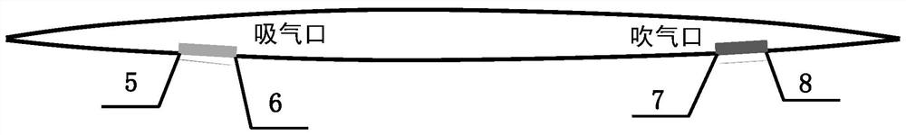
[0101] Set two suction ports and two blow ports (configuration 1)
[0102] Step 1, determine the areas of compression and expansion of the lower surface of the aircraft.
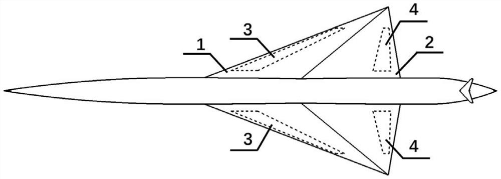
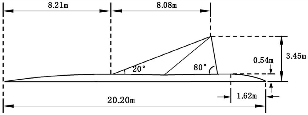
[0103] Using the computational fluid dynamics method, the NS equation is used to numerically simulate the spatial flow field of the reference configuration, where the reference length c of the whole machine is 8.08m, and the reference area S is 16.57m 2 . Calculation status: Mach number Ma is 1.4, Reynolds number Re is 7.32×10 7 , the angle of attack α is 1 degree. The results show that the leading edge 1 of the lower surface of the aircraft and the trailing edge 2 of the lower surface of the aircraft are the main locations where compression waves and expansion waves are generated respectively, so that the positions of the compression region and the expansion region are determined;
[0104] Step 2, install the suction port in the compression area and the blowing port in the expansion area.
[0105] First...
Embodiment 2
[0119] Set four suction ports and four blow ports (configuration 2)
[0120] Step 1, determine the areas of compression and expansion of the lower surface of the aircraft.
[0121] Using the computational fluid dynamics method, the NS equation is used to numerically simulate the spatial flow field of the reference configuration, where the reference length c of the whole machine is 8.08m, and the reference area S is 16.57m 2 . Calculation status: Mach number Ma is 1.4, Reynolds number Re is 7.32×10 7 , the angle of attack α is 1 degree. The results show that the leading edge 1 of the lower surface of the aircraft and the trailing edge 2 of the lower surface of the aircraft are the main locations where compression waves and expansion waves are generated respectively, so that the positions of the compression region and the expansion region are determined;
[0122] Step 2, install the suction port in the compression area and the blowing port in the expansion area.
[0123] Fir...
PUM
 Abstract
Description
Claims
Application Information
 - R&D Engineer
- R&D Manager
- IP Professional
- Industry Leading Data Capabilities
- Powerful AI technology
- Patent DNA Extraction
Browse by: Latest US Patents, China's latest patents, Technical Efficacy Thesaurus, Application Domain, Technology Topic, Popular Technical Reports.
© 2024 PatSnap. All rights reserved.Legal|Privacy policy|Modern Slavery Act Transparency Statement|Sitemap|About US| Contact US: help@patsnap.com