
Air conditioner with double-stage flow guide system for single-centrifugal up-and-down air outlet

A single centrifugal up and down air outlet, air conditioner technology, applied in air conditioning systems, applications, household heating and other directions, can solve problems such as easy noise generation, affecting air conditioning refrigeration and heating efficiency, poor heat exchange effect, etc.

Pending Publication Date: 2021-03-23
GREE ELECTRIC APPLIANCES INC
View PDF1 Cites 0 Cited by
  • Summary
  • Abstract
  • Description
  • Claims
  • Application Information

AI Technical Summary

Problems solved by technology

[0003] In the existing single-centrifugal cabinets with upper and lower air outlets, since the centrifugal fan is located in the middle of the heat exchanger, the wind speed on the side of the air inlet near the fan is faster, which is prone to hidden dangers such as noise; the location of the single centrifugal fan Due to its particularity, the heat exchange effect of the heat exchanger gradually depends on the center position of the heat exchanger, resulting in extremely poor heat exchange effect at the upper and lower top positions of the heat exchanger, which further affects the cooling and heating efficiency of the air conditioner

Method used


Image

  • Air conditioner with double-stage flow guide system for single-centrifugal up-and-down air outlet
  • Air conditioner with double-stage flow guide system for single-centrifugal up-and-down air outlet
  • Air conditioner with double-stage flow guide system for single-centrifugal up-and-down air outlet

Examples


Embodiment Construction

[0025] The following will clearly and completely describe the technical solutions in the embodiments of the present invention with reference to the accompanying drawings in the embodiments of the present invention. Obviously, the described embodiments are only some, not all, embodiments of the present invention.

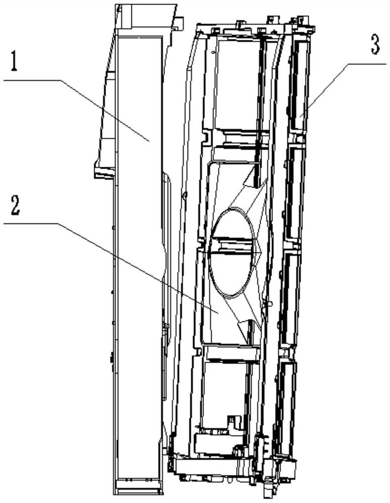
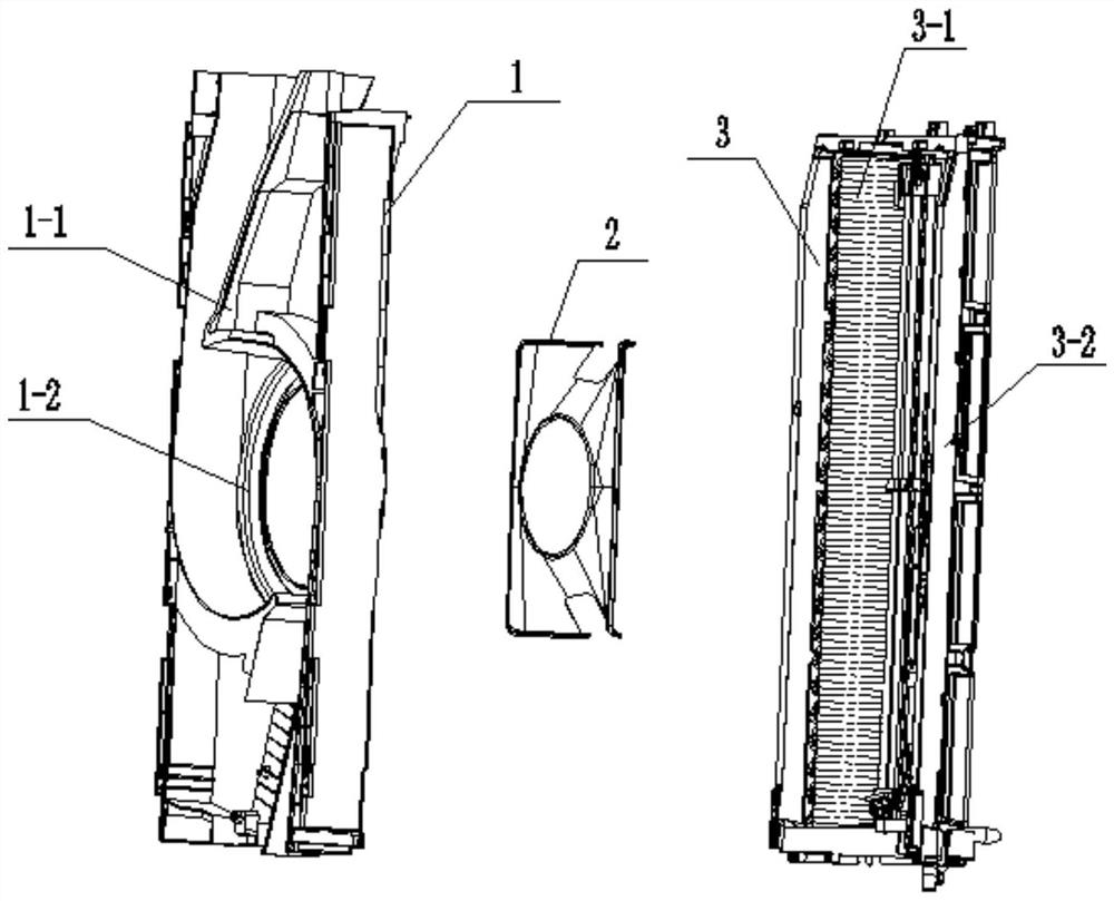
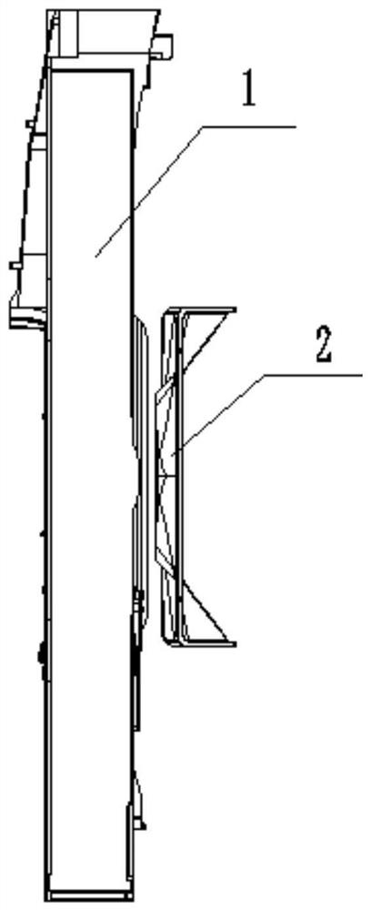
[0026] refer to Figure 1-7 , an air conditioner with a double-stage guide system for single-centrifugal upper and lower air outlets, including an air duct part 1, a guide plate 2 and a heat exchanger part 3, and the guide plate 2 is located between the air duct part 1 and the heat exchanger Between the parts 3, and the deflector 2 is fixedly installed on the side of the heat exchanger part 3 close to the air duct part 1. The air duct part 1 includes the air duct 1-1 and the air guide installed on the air duct 1-1. Circle 1-2, the heat exchanger part 3 includes the evaporator support 3-2 and the evaporator 3-1 fixedly installed on the evaporator support 3-2. The cir...


PUM


Abstract

The invention belongs to the field of air conditioners, and particularly relates to an air conditioner with a double-stage flow guide system for single-centrifugal up-and-down air outlet. The air conditioner comprises an air duct component, a flow guide plate and a heat exchanger component, wherein the flow guide plate is positioned between the air duct component and the heat exchanger component;the flow guide plate is fixedly arranged on one side, close to the air duct component, of the heat exchanger component ; the air duct component comprises an air duct and a flow guide ring arranged onthe air duct; the heat exchanger component comprises an evaporator support and an evaporator fixedly arranged on the evaporator support; the air conditioner further solves the problem that noise is generated at an air inlet of a cabinet air conditioner capable of achieving up-and-down air outlet through single centrifugation, and solves the problem that air inlet of one side of the air inlet position of a single centrifugal fan is not smooth; a refrigeration and heating replacement effect of the air conditioner is enhanced; the rapid refrigeration and heating of the air conditioner are furtherenhanced; the heat exchange effect difference between the center position of the heat exchanger and the upper position of the heat exchanger and between the center position of the heat exchanger andthe lower position of the heat exchanger is reduced; the problem that the air speed of the center position of a single centrifugal fan is high is solved; and the air inlet uniformity of the air inletside of the air conditioner is enhanced.

Description

technical field [0001] The invention relates to the technical field of air conditioners, in particular to an air conditioner with a double-stage flow guide system for single-centrifugal up and down air outlet. Background technique [0002] The patent No. CN201910556927.6 provides an air duct structure and an air conditioner, which relates to the technical field of air conditioners. The air duct structure includes an air duct main body, a deflector and two fans. The two fans are installed one above the other on the main body of the air duct, and one side of the main body of the air duct is set as the air inlet side, and the air inlets of the two fans are all opened on the air inlet side. The deflector is connected to the main body of the air duct and correspondingly disposed between the two fans, and the deflector protrudes from the main body of the air duct. The present invention also provides an air conditioner, which adopts the above-mentioned air duct structure. The air...

Claims


Application Information

Patent Timeline
Patent Type & Authority Applications(China)
IPC IPC(8): F24F1/0014F24F1/0022F24F13/065F24F13/08F24F13/24
CPCF24F1/0014F24F1/0022F24F13/065F24F13/084F24F13/24F24F2013/247
Inventor 林德贤邵家成曾新成罗文君张利林桂林
Owner GREE ELECTRIC APPLIANCES INC
Learn More