Eureka AIR delivers breakthrough ideas for toughest innovation challenges, trusted by R&D personnel around the world.

Ventilation, heat dissipation and noise reduction structure

A technology of ventilation, heat dissipation, and noise reduction, which is applied in the direction of sound insulation, building components, and building structures. It can solve the problems of weak product adaptability, over-immobilization, and weak performance, and achieve improved heat dissipation, improved sealing, and improved functionality. Effect

Inactive Publication Date: 2021-03-23
苏州豹驰声学科技有限公司
View PDF7 Cites 2 Cited by
  • Summary
  • Abstract
  • Description
  • Claims
  • Application Information

AI Technical Summary

Problems solved by technology

[0005] Aiming at the deficiencies of the existing technology, the present invention provides a ventilation and heat dissipation noise reduction structure, which has a modular design to realize multi-band noise reduction, customization of the installation quantity, and control of the noise reduction range, so that the performance and cost requirements are comprehensively considered, and the product performance is consistent The advantages of high reliability, easy control of product quality, and quick application in the noise reduction market solve the traditional single function, which can only be used as noise reduction, and it is inconvenient to adjust, the installation quantity is inconvenient to adjust, too fixed, production High cost, weak product adaptability, and weak performance

Method used


Image

  • Ventilation, heat dissipation and noise reduction structure
  • Ventilation, heat dissipation and noise reduction structure
  • Ventilation, heat dissipation and noise reduction structure

Examples


Embodiment Construction

[0027] The following will clearly and completely describe the technical solutions in the embodiments of the present invention with reference to the accompanying drawings in the embodiments of the present invention. Obviously, the described embodiments are only some, not all, embodiments of the present invention. Based on the embodiments of the present invention, all other embodiments obtained by persons of ordinary skill in the art without making creative efforts belong to the protection scope of the present invention.

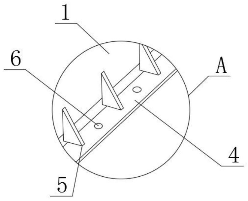
[0028] see Figure 1-5 , a ventilation and heat-dissipating sound-absorbing structure, including a product sound insulation cover 1, the top outer surface of the product sound insulation cover 1 is provided with multiple groups of sound-absorbing units 2, the sound-absorbing frequency of the sound unit can be customized, and the sound-absorbing amplitude can be customized. For the compatibility between the device and the product, it is generally necessary to a...


PUM


Abstract

The invention relates to the technical field of noise reduction structures, and discloses a ventilation and heat dissipation noise reduction structure. The structure comprises a product acoustic hood,wherein multiple noise reduction units are arranged on the outer surface of the top of the product acoustic hood, mounting rods penetrating through the outer surfaces of the tops of the noise reduction units are arranged on the outer surfaces of the bottoms of the noise reduction units, a mounting plate is arranged on the outer surface of the outer side of the bottom of the product acoustic hood,multiple supporting plates are arranged on the outer surface of the top of the mounting plate and located on the outer surface of the outer side of the product acoustic hood, mounting holes are formed between every two adjacent supporting plates and located in the outer surface of the top of the mounting plate, multiple mounting openings are formed in the outer surface of the outer side of the product acoustic hood, and multiple positioning grooves are formed in the outer surfaces of the outer sides of the mounting rods and located in the outer surface of the top of the noise reduction units.The ventilation, heat dissipation and noise reduction structure is used for improving a noise reduction function of products such as a conventional ventilation acoustic hood, or other product heat dissipation windows, and meanwhile the comprehensive effect of cooling and noise reduction is achieved.

Description

technical field [0001] The invention relates to the technical field of ventilation and noise reduction technology, in particular to a ventilation, heat dissipation and noise reduction structure. Background technique [0002] With the improvement of people's living standards, vibration and noise comfort requirements have become the key technical indicators in product development. In order to meet the market's comfort requirements for products, low-noise design has become one of the main performance indicators of products. For special applications Scenarios, during the design process of the product, it is necessary to meet the requirements of ventilation and heat dissipation, and at the same time, it is necessary to take into account the effect of noise reduction. However, ventilation and noise reduction are often contradictory, and a large ventilation area will inevitably lead to attenuation of noise reduction capabilities. [0003] The existing noise reduction structure has ...

Claims


Application Information

Patent Timeline
IPC IPC(8): E04B1/82G10K11/16G10K11/162
CPCE04B1/8218G10K11/16G10K11/162
Inventor 孙新波
Owner 苏州豹驰声学科技有限公司
Why Eureka
Eureka Blog
Learn More