Vibration feeding device for screws

A feeding device and screw technology, applied in metal processing, metal processing equipment, manufacturing tools, etc., can solve the problems of slow feeding speed, lack of versatility, high failure rate, etc., and achieve the effect of improving work efficiency

Pending Publication Date: 2021-03-23
深圳市森阳智能制造装备有限公司
View PDF0 Cites 3 Cited by
  • Summary
  • Abstract
  • Description
  • Claims
  • Application Information

AI Technical Summary

Problems solved by technology

[0007] In order to solve the problems of slow feeding speed, high failure rate and lack of versatility of the screw machine feeder in the prior art, the present invention provides a screw vibrating feeding device

Method used


Image

  • Vibration feeding device for screws
  • Vibration feeding device for screws
  • Vibration feeding device for screws

Examples


Embodiment Construction

[0022] In order to explain the technical solution of the present invention more clearly, the embodiments of the present invention will be briefly described below in conjunction with the accompanying drawings. Obviously, the description of the embodiments and the accompanying drawings is only to illustrate the technical solutions of the present invention. Under the background that those of ordinary skill in the art can understand, the scope of protection of the present invention is not limited to the embodiments and accompanying drawings.

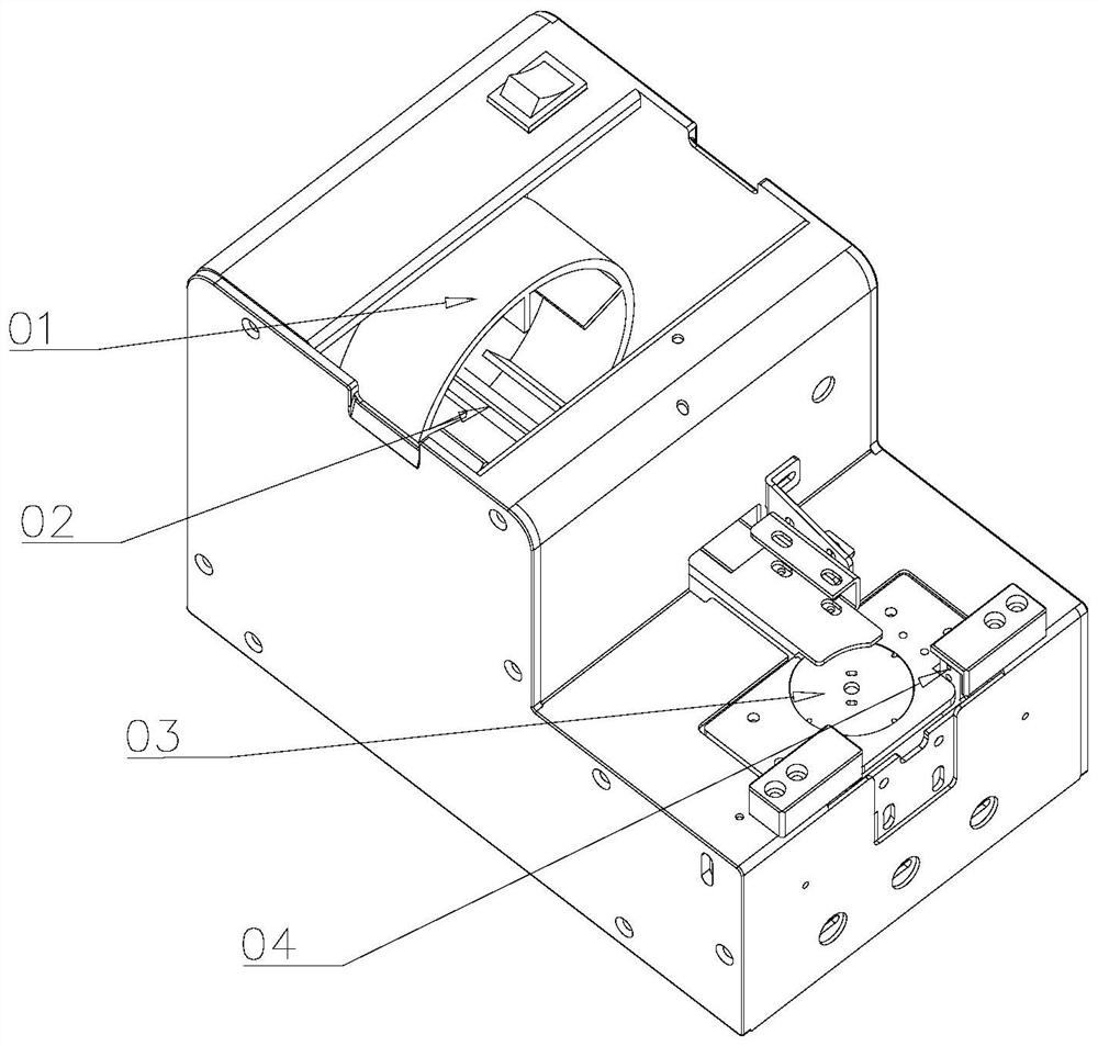
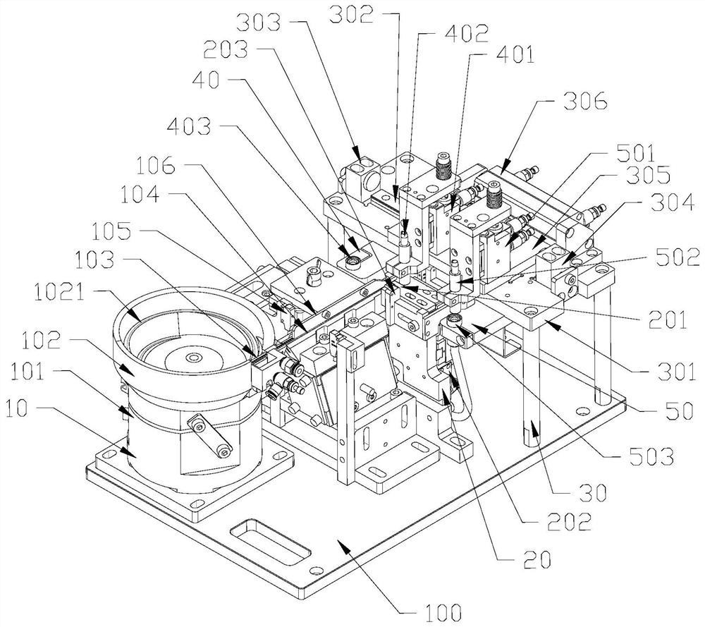
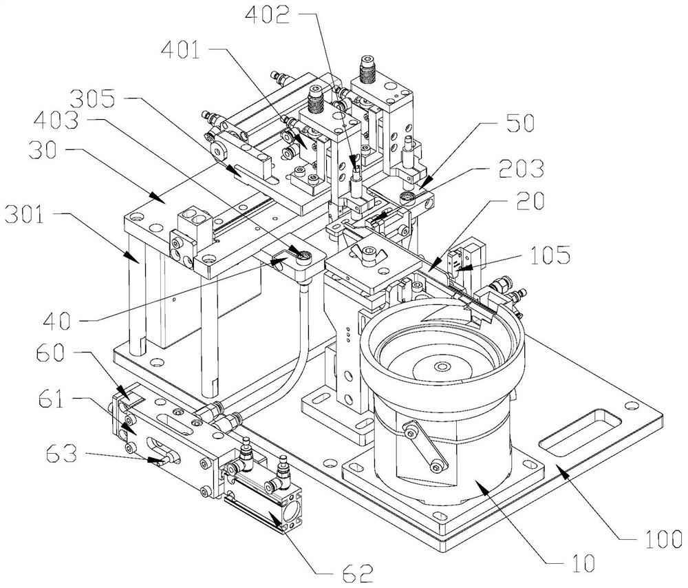
[0023] Such as figure 2 , 3 Shown, be a kind of screw vibrating feeding device, comprise bottom plate 100, be arranged on the feeding part 10 above described bottom plate 100, distributing part 20 and channel part 30, described channel part 30 is formed by first channel part 40 , the second channel part 50 and the confluence 60, wherein, the first channel part 40 and the second channel part 50 are respectively communicated with the conflue...


PUM


Abstract

The invention provides a vibration feeding device for screws. The vibration feeding device for the screws comprises a bottom plate, a feeding part, a distributing part and a channel part, the feedingpart, the distributing part and the channel part are arranged on the bottom plate, the channel part is composed of a first channel part, a second channel part and a junction station, the first channelpart and the second channel part both communicate with the junction station, and the junction station is used for providing the screws, with determined positions, used for locking operation for a locking suction head of a screw machine. According to the technical scheme of the vibration feeding device for the screws, due to the fact that structural optimization design is carried out on the vibration feeding device of the screw machine, the vibration feeding device is suitable for the screws of different specifications and particularly suitable for tiny fine screws, meanwhile, the problems ofclamping stagnation and the like caused by abrasion of equipment are solved, and the working efficiency is greatly improved.

Description

technical field [0001] The invention relates to the technical field of automatic screw locking, in particular to a vibrating feeding device suitable for fine small screws in a screw machine. Background technique [0002] In recent years, the electronics industry has developed rapidly, and the requirements for the manufacturing technology of electronic products are getting higher and higher. The production line of electronic products has more and more processes and becomes more and more complicated. Among them, locking screws is a very complicated and demanding task. basic work. The traditional screw locking equipment has low precision, complex operation and poor versatility. With the continuous improvement of technical requirements, the new generation of screw locking equipment gradually has the characteristics of high precision, simple operation and strong versatility. [0003] The screw locking machine generally includes a feeding part for supplying materials (screws) an...

Claims


Application Information

Patent Timeline
Patent Type & Authority Applications(China)
IPC IPC(8): B23P19/06B23P19/00
CPCB23P19/06B23P19/00B23P19/001
Inventor 张艳张垒
Owner 深圳市森阳智能制造装备有限公司
Why Eureka
Try Eureka