fireproof cable

A fireproof cable and cable technology, applied in the direction of insulated cables, cables, circuits, etc., can solve the problems of casualties, surface damage, battery damage, etc., and achieve the effect of preventing flame damage and increasing fire resistance

Active Publication Date: 2022-05-10
沧州会友线缆股份有限公司
View PDF15 Cites 0 Cited by
  • Summary
  • Abstract
  • Description
  • Claims
  • Application Information

AI Technical Summary

Problems solved by technology

[0002] The field of cable setting is very wide, and most of them are laid in building buildings or underground cable wells. However, no matter where the cables are laid, because the cables are laid in a large number, once one of the cables is ignited, it is easy to cause a fire, especially in the For the cables in the shaft of the building, once there is a fire source somewhere, when one cable is ignited, it will quickly spread to other cables, causing all the cables to be ignited, and the fire source will go up along the cable, This will cause the flame to reach other building floors along the shaft, which will lead to the rapid transmission of the flame in the building, causing the building to catch fire and causing serious casualties. Therefore, the fire protection requirements for cables laid in the building shaft will be higher.
[0003] There are many fireproof cables in the prior art. The common way for these fireproof cables is to set the structure of the outer protective layer of the cable as a fireproof structure, and we know that the fireproof structure is not completely afraid of flames, but can burn in flames. It has a flame retardant performance, but after burning it for a long time, the surface layer will form a carbonized layer, but if the flame continues to burn at this time, after a period of time, the surface layer will still be It will be destroyed, and the high temperature will damage the internal batteries, so the fireproof outer protective layer can only withstand fireproofing for a period of time, and cannot keep fireproofing indefinitely, so once the fire-resistant time is reached, its surface layer will still be destroyed

Method used


Image

  • fireproof cable
  • fireproof cable
  • fireproof cable

Examples


Embodiment Construction

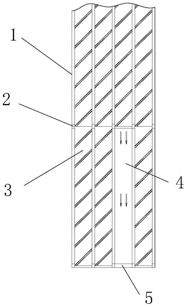
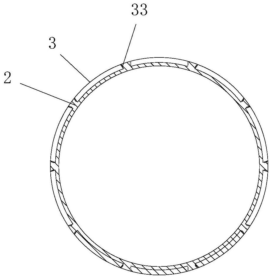
[0018] Such as figure 1 As shown, a fireproof cable includes more than one strand of cables vertically arranged in the cable shaft, each strand of cable includes more than one fixing ring 2 and more than one connecting rod 1 arranged between adjacent fixing rings 2, The connecting rod 1 is evenly arranged around the fixed ring 2;

[0019] A sealing cavity 4 is formed between adjacent connecting rods 1, and each sealing cavity 4 is sealed by a sealing sheet 3 with fireproof capability. The sheet 3 is loaded from the sliding cavity and sealed in each sealing cavity 4 , the upper and lower ends of each sealing sheet 3 are respectively butted and contacted and the upper and lower ends of the sealing sheet 3 are located in the sliding cavity 5 of the adjacent sealing cavity 4 .

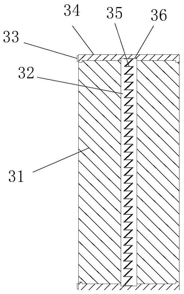
[0020] In this example, if figure 2 As shown, the sealing sheets 3 all include a flexible main body portion 31, and a metal wrapping 34 is respectively arranged on the upper and lower ends of the flexib...


PUM


Abstract

The invention discloses a fireproof cable, which comprises more than one strand of cables vertically arranged in a cable shaft, each strand of cable includes more than one fixing ring and more than one connecting rod between adjacent fixing rings, the connecting rod It is evenly arranged along the fixed ring; a sealed cavity is formed between adjacent connecting rods, and each sealed cavity is sealed by a sealing sheet with fireproof capability. The fixed ring is provided with a corresponding seal facing the sealed cavity. The sliding chambers, the sealing sheets are loaded from the sliding chambers and seal each sealing chamber, the upper and lower ends of each sealing sheet are respectively butted and contacted and the upper and lower ends of the sealing sheets are located in the sliding chambers of the adjacent sealing chambers. The whole cable of the present invention is wrapped and sealed by more than one sealing sheet, which has very good fireproof ability, and can quickly replace the sealing sheet after being subjected to flame, so that the cable can be in an optimal fireproof state for a long time.

Description

technical field [0001] The invention relates to a cable, in particular to a fireproof cable. Background technique [0002] The field of cable setting is very wide, and most of them are laid in building buildings or underground cable wells. However, no matter where the cables are laid, because the cables are laid in a large number, once one of the cables is ignited, it is easy to cause a fire, especially in the For the cables in the shaft of the building, once there is a fire source somewhere, when one cable is ignited, it will quickly spread to other cables, causing all the cables to be ignited, and the fire source will go up along the cable, In turn, the flame will reach other building floors along the shaft, which will cause the flame to spread rapidly in the building, cause the building to catch fire, and cause serious casualties. Therefore, the fire protection requirements for cables laid in the building shaft will be higher. [0003] There are many fireproof cables in ...

Claims


Application Information

Patent Timeline
Patent Type & Authority Patents(China)
IPC IPC(8): H01B7/29
CPCH01B7/29
Inventor 王章力
Owner 沧州会友线缆股份有限公司
Why Eureka
Try Eureka