


Quick Research
Generate reliable direction feasibility study reports for your R&D in just a few steps.

Technical Q&A
Discover and master advanced knowledge NOW. Basics, ideas, possibilities, all at once.

Find Solutions
As an expert in R&D theories, this can generate solutions to your technical problems instantly.

Evaluate Feasibility
Analyze your overall solution with one click, know your potential R&D risks in advance.

Monitor Landscape
Get weekly tech updates, stay abreast of the latest tech innovations and key insights.
Strip-shaped plate scribing device for mechanical production
A scribing device and plate technology, which is applied to workshop equipment, manufacturing tools, etc., can solve the problems of no protection, unstable plate fixing, time-consuming and labor-intensive problems, etc.
- Summary
- Abstract
- Description
- Claims
- Application Information
AI Technical Summary
Problems solved by technology
Method used
Image

Examples
specific Embodiment approach 1
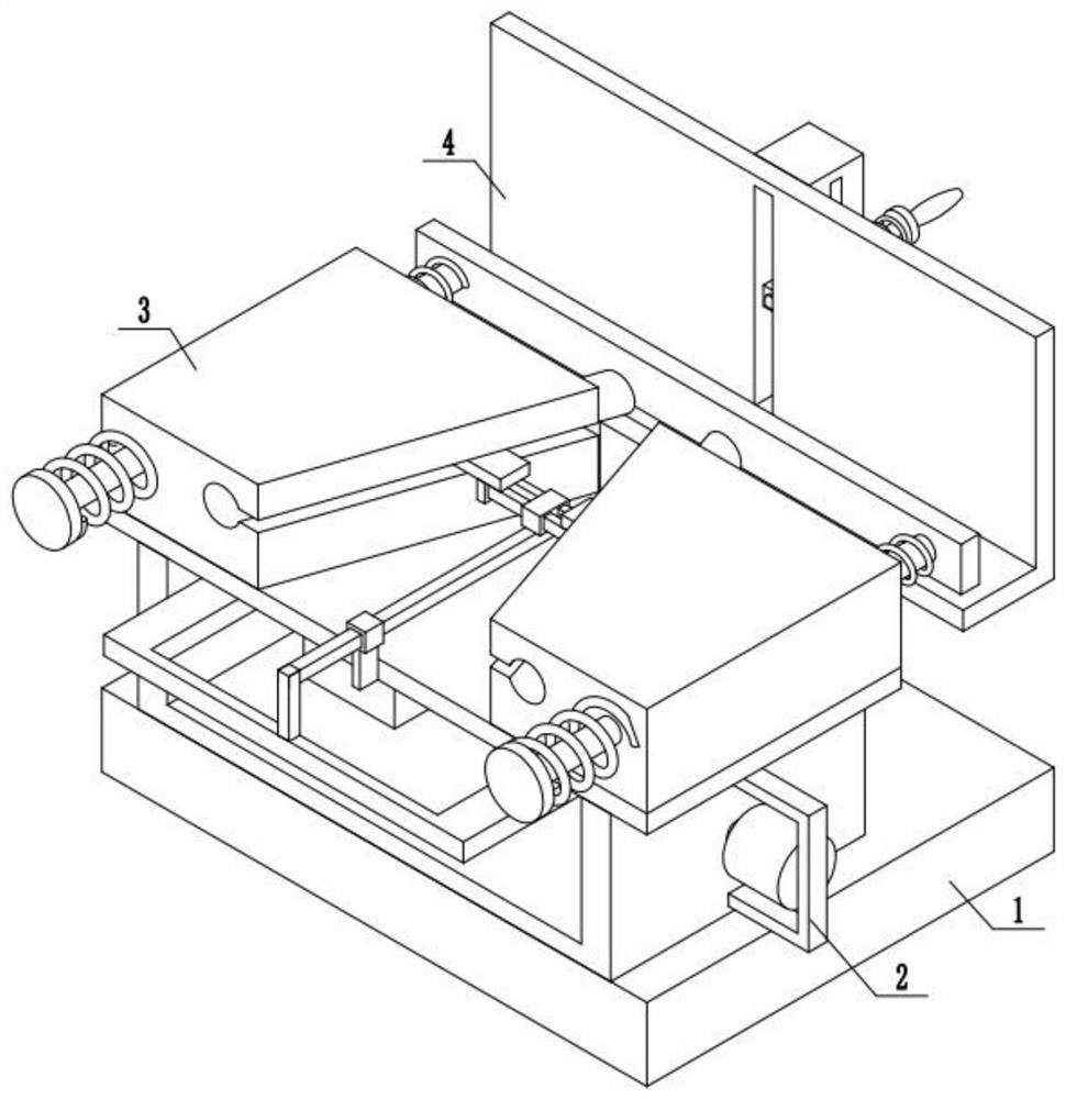
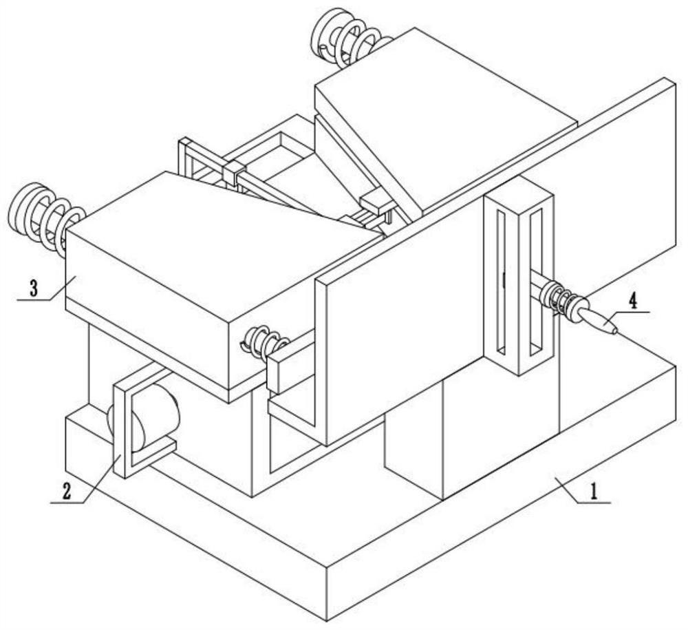
[0037] Combine below figure 1 , 2 Description of this embodiment, a strip-shaped plate marking device for mechanical production, including a fixed base 1, a feed drive device 2, a clamping push device 3 and a marking device 4, the feed drive device 2 is fixed and installed on On the top of the fixed base 1, a marking device 4 is fixedly installed on the top of the fixed base 1, and the clamping and pushing device 3 is installed on the top of the feed driving device 2.
specific Embodiment approach 2
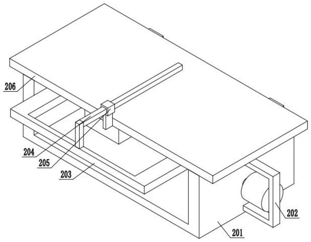
[0039] Combine below image 3 , 4 , 5, 6 illustrate this embodiment, and this embodiment will further explain Embodiment 1. The described feed driving device 2 includes a bottom frame body 201, a power motor A202, a driving mechanism 203, a driving slide bar 204, and a fixed sliding sleeve 205 1. Fix the upper seat plate 206, the bottom frame body 201 is fixedly installed with a power motor A202, the output end of the power motor A202 is equipped with a driving mechanism 203, and the driving mechanism 203 is fixedly installed with a driving slide bar 204, and the driving slide bar 204 is slidably installed on a fixed On the sliding sleeve 205, the fixed sliding sleeve 205 is fixedly installed on the fixed upper seat plate 206, and the bottom frame body 201 is fixedly installed under the fixed upper seat plate 206;
[0040] Described driving mechanism 203 comprises driving screw rod 207, limit block 208, screw thread driving block 209, power motor B210, driving pulley A211, dr...
specific Embodiment approach 3
[0042] Combine below Figure 7 , 8 , 9, 10, and 11 illustrate this embodiment, and this embodiment will further explain Embodiment 1. The clamping and pushing device 3 includes a transmission mechanism 301, a guide sliding sleeve 302, a guide rod 303, a spring A304, a spring B305, a push plate 306, the transmission mechanism 301 is fixedly installed on the driving slide bar 204, the transmission mechanism 301 is slidably installed on the guide sliding sleeve 302, the guide rod 303 is slidably installed on the guide sleeve 302, the spring A304 is set on the guide rod 303, and the spring A304 The two ends of the spring B305 are respectively fixedly installed on the guide rod 303 and the guide sliding sleeve 302, the spring B305 is set on the guide rod 303, and the two ends of the spring B305 are respectively fixedly installed on the guide sleeve 302 and the push plate 306, and the push plate 306 is fixedly installed on the guide rod 303;
[0043] The transmission mechanism 301...
PUM
 Abstract
Description
Claims
Application Information
 - R&D Engineer
- R&D Manager
- IP Professional
- Industry Leading Data Capabilities
- Powerful AI technology
- Patent DNA Extraction
Browse by: Latest US Patents, China's latest patents, Technical Efficacy Thesaurus, Application Domain, Technology Topic, Popular Technical Reports.
© 2024 PatSnap. All rights reserved.Legal|Privacy policy|Modern Slavery Act Transparency Statement|Sitemap|About US| Contact US: help@patsnap.com