A processing device for fastening fixtures of lighting fixtures
A technology for processing devices and lighting fixtures, applied in positioning devices, storage devices, feeding devices, etc., which can solve the problems of single structure, inability to fix sheet drilling, cutting or bending, etc., and achieve the effect of single function
- Summary
- Abstract
- Description
- Claims
- Application Information
AI Technical Summary
Problems solved by technology
Method used
Image

Examples
specific Embodiment approach 1
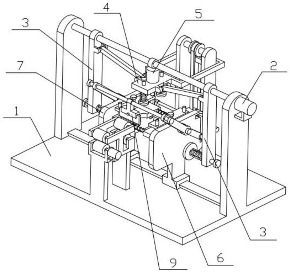
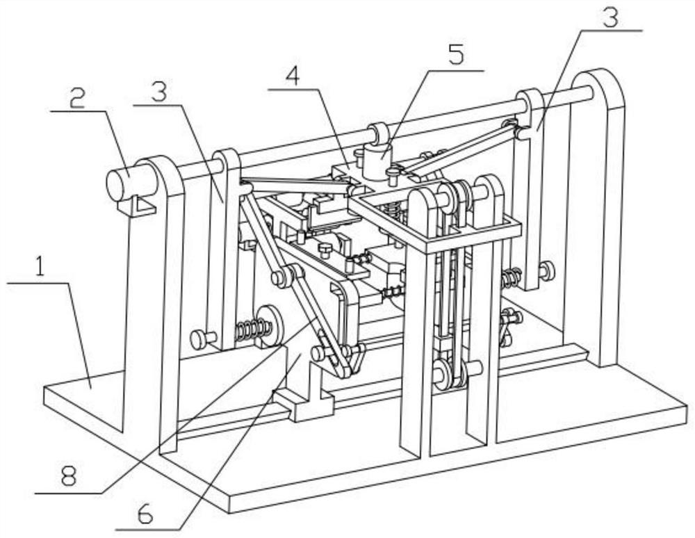
[0037] Combine below Figure 1-13 Description of this embodiment, a processing device for fixtures of lighting fixtures that is convenient for clamping, including a chassis mechanism 1, a power mechanism 2, a pull-down top tightening mechanism 3, a pressing mechanism 4, a drilling mechanism 5, a workbench mechanism I6, Workbench mechanism II7, bending mechanism 8 and cutting mechanism 9, the power mechanism 2 is connected to the top of the chassis mechanism 1, the pull-down clamping mechanism 3 is connected to the power mechanism 2, and the pressing mechanism 4 is connected to the pull-down clamping mechanism 3, the drilling mechanism 5 is connected to the pressing mechanism 4, the workbench mechanism I6 and the workbench mechanism II7 are connected to the middle of the chassis mechanism 1, the bending mechanism 8 and the cutting mechanism 9 are connected to the workbench mechanism I6 and the workbench Institution II7. The simultaneous action of the power mechanism 2 and the ...
specific Embodiment approach 2
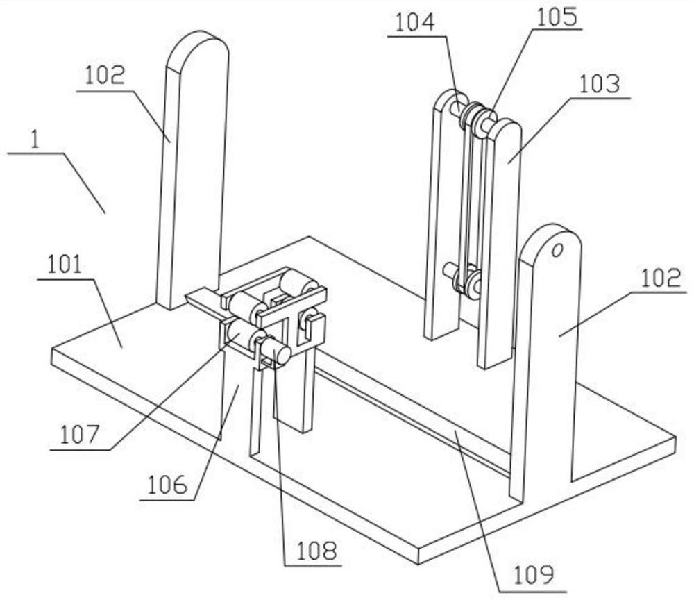
[0038] Combine below Figure 1-13 Describe this embodiment, this embodiment will further explain Embodiment 1. The underframe mechanism 1 includes a bottom plate 101, a side plate 102, a rear plate 103, a rotating shaft 104, a sprocket wheel 105, a front bracket 106, a material guide roller 107, Geared motor I 108 and slideway 109 are fixedly connected with side plates 102 on the left and right sides of the base plate 101, and are fixedly connected with a rear plate 103 at the rear of the base plate 101, and are rotatably connected with a rotating shaft 104 at the upper and lower parts of the rear plate 103, The middle part of each rotating shaft 104 is fixedly connected with a sprocket 105, and the two sprockets 105 are connected by a transmission chain. The guide roller 107 is connected, the reduction motor I 108 is fixedly connected to the front bracket 106, the output shaft of the reduction motor I 108 is fixedly connected to one of the guide rollers 107, and the slideway ...
specific Embodiment approach 3
[0039] Combine below Figure 1-13 Describe this embodiment, this embodiment will further explain the second embodiment, the power mechanism 2 includes a geared motor II 201, a double-threaded screw 202 and a limit ring 203, and the geared motor II 201 is fixedly connected to the side plate 102 on the right side One end of the double-threaded screw 202 is fixedly connected to the output shaft of the geared motor II 201, the other end of the double-threaded screw 202 is rotatably connected to the upper end of the side plate 102 on the left side, and the limit ring 203 is fixedly connected to the double-threaded screw 202 Central. When in use, the geared motor II 201 is in the working state, and the output shaft of the geared motor II 201 will drive the double-thread screw 202 to rotate around the output shaft of the geared motor II 201. The positive and negative rotation of the reduction motor II 201 can control the two pull-down clamping mechanisms 3 to approach or move away f...
PUM
 Abstract
Description
Claims
Application Information
 - R&D
- Intellectual Property
- Life Sciences
- Materials
- Tech Scout
- Unparalleled Data Quality
- Higher Quality Content
- 60% Fewer Hallucinations
Browse by: Latest US Patents, China's latest patents, Technical Efficacy Thesaurus, Application Domain, Technology Topic, Popular Technical Reports.
© 2025 PatSnap. All rights reserved.Legal|Privacy policy|Modern Slavery Act Transparency Statement|Sitemap|About US| Contact US: help@patsnap.com