Automatic blanking device of hardware stamping die
A technology of stamping die and blanking device, which is applied in the direction of feeding device, positioning device, storage device, etc., can solve the problems of quality degradation of stamping parts, drop damage of stamping parts, poor adsorption between suction cups and stamping parts surface, etc. Improve the efficiency of stamping processing and the quality of stamping parts, and the effect of quick pick and place
- Summary
- Abstract
- Description
- Claims
- Application Information
AI Technical Summary
Problems solved by technology
Method used
Image
Examples
Embodiment 1
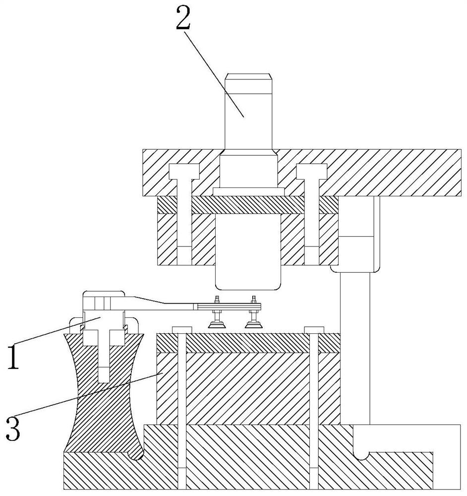
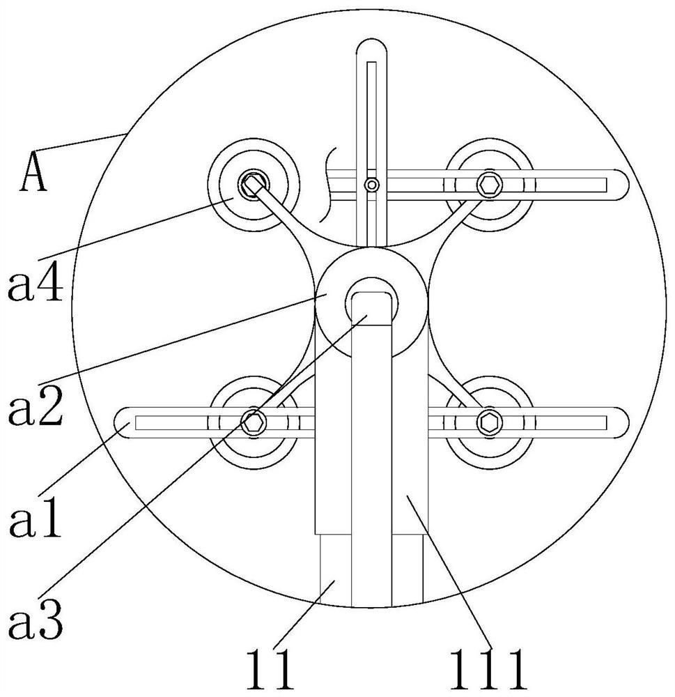
[0027] Such as Figure 1-6 As shown, the present invention provides an automatic blanking device for metal stamping dies, including an automatic loading and unloading mechanism 1, a stamping head 2 and a stamping table 3, the bottom of the stamping head 2 is provided with an upper surface of the stamping table 3, and the bottom of the stamping table 3 The front end of the upper surface is provided with the rear end of the automatic loading and unloading mechanism 1, the lower surface of the stamping head 2 is provided with the rear end of the automatic loading and unloading mechanism 1, the upper surface of the support table 10 is fixedly connected with a rotary drive, and the rear end of the rotary drive is connected to the movable rod. The front end of 11 is movably connected, and the front end of movable rod 11 is movably connected with the right end of air pump 12 through the top of support platform 10, and the front end of movable rod 11 is fixedly connected with adsorptio...
Embodiment 2
[0031] Such as Figure 5 , Image 6 , Figure 7As shown, on the basis of Example 1, the present invention provides a technical solution: the bottom of the silicone rubber suction bottom b4 is provided with an adsorption chamber d1, the inner wall of the adsorption chamber d1 is evenly provided with silicone rubber protrusions d5, and the surface of the adsorption chamber d1 The inner wall is evenly opened with a special-shaped groove d3, the upper and lower ends of the special-shaped groove d3 are fixedly connected with one side of the pneumatic chamber d2, the bottom of the pneumatic chamber d2 is provided with a sand leakage groove, and the bottom of the special-shaped groove d3 near the side of the pneumatic chamber d2 is flexibly connected There is a stopper d4, the rear end of the stopper e1 is inserted into the bottom inner wall of the special-shaped groove d3, the top of the rear end of the stopper e1 is movably connected with one end of the spring e2, and the other en...
PUM
 Abstract
Description
Claims
Application Information
 - R&D
- Intellectual Property
- Life Sciences
- Materials
- Tech Scout
- Unparalleled Data Quality
- Higher Quality Content
- 60% Fewer Hallucinations
Browse by: Latest US Patents, China's latest patents, Technical Efficacy Thesaurus, Application Domain, Technology Topic, Popular Technical Reports.
© 2025 PatSnap. All rights reserved.Legal|Privacy policy|Modern Slavery Act Transparency Statement|Sitemap|About US| Contact US: help@patsnap.com


