
Suspended fiber distribution box for Internet communication

An Internet communication and suspension technology, applied in the field of communication, can solve problems such as the influence of internal components, achieve the effect of improving the convenience of use, easy to clean and use, and ensuring the effect of heat dissipation

Inactive Publication Date: 2021-03-16
周海朝
View PDF0 Cites 1 Cited by
  • Summary
  • Abstract
  • Description
  • Claims
  • Application Information

AI Technical Summary

Problems solved by technology

[0003] However, the existing fiber distribution box is mostly a closed box, and the internal heat is taken out by sending the outside air into the inside. However, when the fiber distribution box is used outdoors, especially in rainy weather, rainwater easily follows the air into the air. The inside of the fiber distribution box will affect the internal components. Therefore, it is necessary to improve the existing fiber distribution box to solve the above problems

Method used


Image

  • Suspended fiber distribution box for Internet communication
  • Suspended fiber distribution box for Internet communication
  • Suspended fiber distribution box for Internet communication

Examples


Embodiment 1

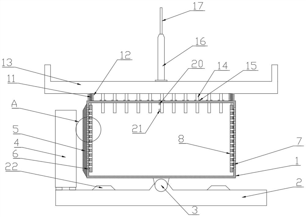
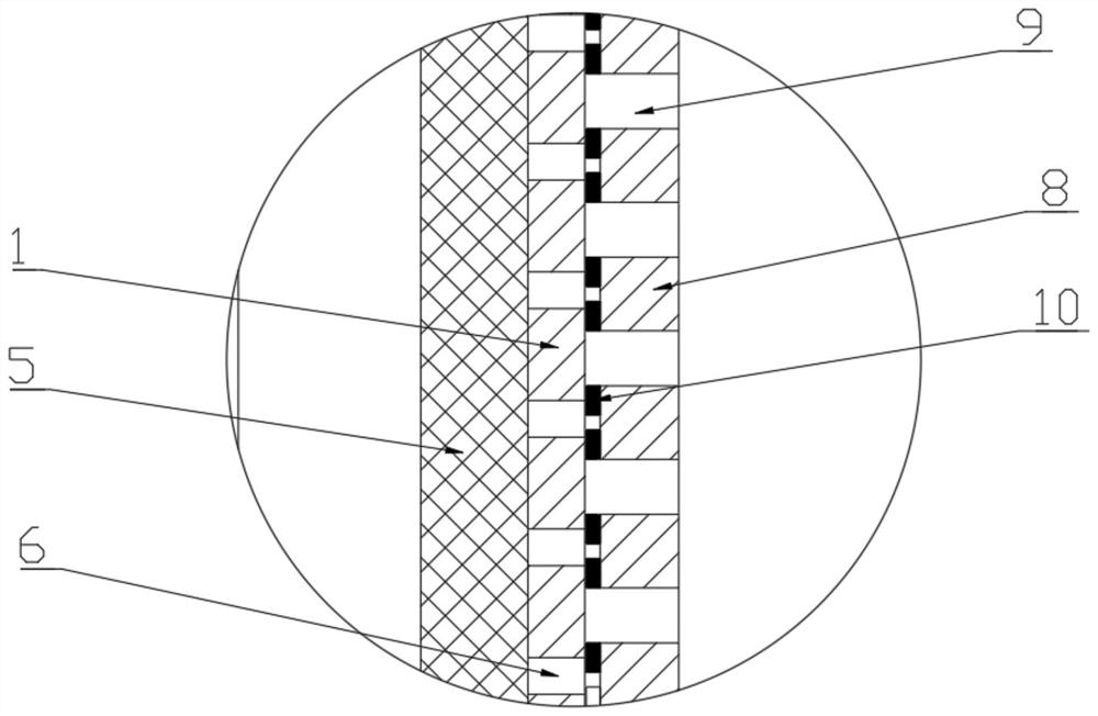
[0021] Please refer to the figure, in the embodiment of the present invention, a suspension type fiber distribution box for Internet communication, including a box body 1, a support base 2, a rotating shaft 3, a fan 4 and a dust-proof net 5; the box body 1 is arranged on the support base Above 2, between the box body 1 and the support base 2, the horizontal shaft 3 is rotated and connected, so that the box body 1 can change the inclination angle in the vertical direction, which is convenient for the dust and water flow on the box body 1; in the box body The upper surface of the support seat 2 directly below the two ends of the bottom of 1 is fixed with an upwardly protruding buffer block 22, and the bottom of the box body 1 is in contact with the buffer block 22 when it swings left and right, so as to protect the bottom of the box body 1; The left side of the box 1 is equipped with a fan 4 fixed on the support base 2, and the fan 4 faces the side wall of the box 1, blowing the ...

Embodiment 2

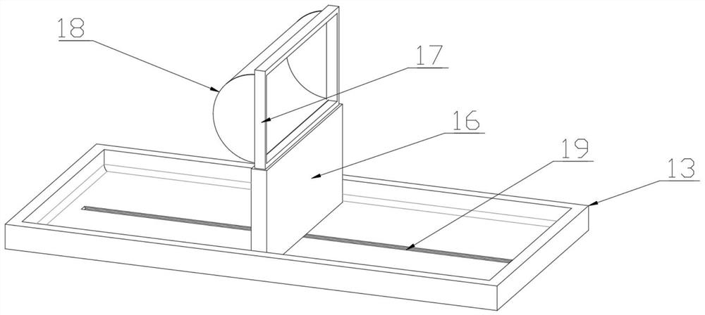
[0026]On the basis of Embodiment 1, the bottom in the rainwater collection tank 13 is provided with a chute 19 along the horizontal direction, and a moving seat 16 is slidably installed in the chute 19, and the moving seat 16 moves in the left and right directions, A vertical blast frame 17 is fixed on the top of the mobile seat 16, and the blast frame 17 is a rectangular frame structure, and a blast curtain 18 is installed in the blast frame 17, and the blast curtain 18 is a bag-shaped structure, and the opening is fixed around the On the peripheral edges of the blasting frame 17, the opening of the blasting curtain 18 is stretched, and when the wind is blown on the blasting frame 17, the movable seat 16 is driven to move under the effect of the blasting curtain 18, preferably, the blasting The material of the air curtain 18 is gauze, which is convenient for the air blast curtain 18 to move conveniently according to the wind direction. Through the effect of the air blast frame...


PUM


Abstract

The invention relates to the field of communication, and particularly discloses a suspended fiber distribution box for Internet communication, and the box comprises a box body, a supporting seat, a rotating shaft, a fan and a dustproof net; a rainwater collecting tank which is horizontally upward is arranged above the box body, vertical connecting rods are fixed to the left end and the right end of the bottom of the rainwater collecting tank, the outer sides of the connecting rods are sleeved with supporting springs, and the lower ends of the connecting rods are fixedly connected with sealingbaffles which are vertically attached to the inner walls of the box body on the left side and the right side. And through holes in one-to-one correspondence with an air inlet hole and an air outlet hole are formed in the sealing baffles. The interior of the box body can be sealed through the arranged rainwater collecting tank in rainy days, meanwhile, operation of the fan is interrupted, the interior of the box body is kept sealed, rainwater is prevented from entering the box body, meanwhile, a heat conduction rod extending into the box body takes away heat in the box body to replace air blowing for heat dissipation, and the heat dissipation effect in the box body is guaranteed; the device is convenient and rapid to switch in rainy days, manual management is not needed, and the use convenience of the device is improved.

Description

technical field [0001] The invention relates to the communication field, in particular to a suspended fiber distribution box for Internet communication. Background technique [0002] The optical fiber distribution box is an interface device used to connect the main optical cable and the distribution optical cable outdoors or indoors. The optical fiber distribution box adopts an inner and outer two-layer structure. It consists of a fiber storage device, and the inner layer is equipped with a fiber splicing disc and a leather cable splicing disc, etc. [0003] However, the existing fiber distribution box is mostly a closed box, and the internal heat is taken out by sending the outside air into the inside. However, when the fiber distribution box is used outdoors, especially in rainy weather, rainwater easily follows the air into the air. The interior of the fiber distribution box affects the internal components. Therefore, it is necessary to improve the existing fiber distrib...

Claims


Application Information

Patent Timeline
Patent Type & Authority Applications(China)
IPC IPC(8): G02B6/44H05K7/20
CPCG02B6/4436G02B6/4446H05K7/20145H05K7/20172H05K7/20181
Inventor 周海朝
Owner 周海朝
Learn More