
Radar level meter

A radar level meter, the technology on the other side, applied in the field of level meter, can solve the problem that the support structure is not easy to disassemble, and achieve the effects of improving the scope of application, facilitating replacement, and improving practicability

Inactive Publication Date: 2021-03-16
陕西诺盈自动化仪表有限公司
View PDF3 Cites 0 Cited by
  • Summary
  • Abstract
  • Description
  • Claims
  • Application Information

AI Technical Summary

Problems solved by technology

[0005] The purpose of the present invention is to provide a radar level gauge to solve the problem that the supporting structure is fixed and not easy to disassemble in the above-mentioned background technology

Method used


Image

  • Radar level meter
  • Radar level meter
  • Radar level meter

Examples


Embodiment 1

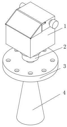
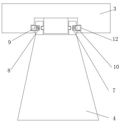
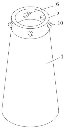
[0021] Example 1 as Figure 1-4 As shown, a radar level gauge includes a controller housing 1, the bottom end of the controller housing 1 is fixedly connected with a connecting block 2, the bottom end of the connecting block 2 is fixedly connected with a support plate 3, and the inner side of the support plate 3 is provided with a card slot 11 One side of the card slot 11 is evenly provided with multiple groups of second limiting grooves 12, the second limiting grooves 12 are fixedly connected with the limiting block 9 through the first positioning block 10, and the other side of the limiting block 9 is fixedly connected with a spring 8 , the other side of the spring 8 is fixedly connected with the first limiting groove 7, the first limiting groove 7 is embedded in the outer side of the connecting ring 5, and the inner side of the connecting ring 5 is evenly provided with multiple groups of chute 6, and the chute 6 and the second positioning The block 13 is engaged and connect...

Embodiment 2

[0022] Embodiment 2 is on the basis of embodiment 1 such as Figure 5 As shown, the top side of the controller housing 1 is rotatably connected to the rubber strip 15 through the rotating shaft 14 , the other side of the rubber strip 15 is fixedly connected to the cover plate 16 , and the bottom end of the cover plate 16 is engaged with the bump 17 .

Embodiment 3

[0023] Embodiment 3 is such as on the basis of embodiment 1 Figure 3-4 As shown, the chute 6 and the second limiting groove 12 are set as arc-shaped slots, and the bottom end of the arc-shaped slots is set as a slant plate.


PUM


Abstract

The invention discloses a radar level meter which comprises a controller shell, a connecting block is fixedly connected to the bottom end of the controller shell, a supporting plate is fixedly connected to the bottom end of the connecting block, a clamping groove is formed in the inner side of the supporting plate, a plurality of sets of second limiting grooves are evenly formed in one side of theclamping groove, and the second limiting grooves are fixedly connected with limiting blocks through first positioning blocks; according to the radar level meter, a worker rotates the supporting frame, the supporting frame is connected with the second positioning block in a clamped mode through the sliding groove, the supporting frame drives the connecting ring to move out from the limitation of the sliding groove, the connecting ring drives the first positioning block to move out from the limitation of the second limiting groove, the first positioning block is limited by the clamping groove,and the spring is in an elastic deformation state to pull the supporting frame; the connecting ring is connected with the clamping groove in a clamped mode, so that the supporting frame is moved out of the supporting plate, the operation of replacing the supporting structure is completed, the damaged supporting frame can be replaced conveniently, supporting structures of different detection sitescan be installed conveniently, and the application range of the device is widened.

Description

technical field [0001] The invention relates to the technical field of a level gauge, in particular to a radar level gauge. Background technique [0002] Microwave level gauge, commonly known as radar (Radar) level gauge, radar level gauge uses microwave pulse measurement method, and can be normal in the industrial frequency band range, the beam energy is low, and can be installed in various metal and non-metal containers or In the pipeline, the non-contact continuous measurement of the level of liquid, slurry and granular material is suitable for occasions where dust, temperature and pressure change greatly, and inert gas and steam exist. The radar level gauge is harmless to the human body and the environment. damage, and is not affected by the specific gravity of the medium, and is not affected by the change of the dielectric constant. The existing radar level gauges are various and have basically met people's daily needs, but there are still deficiencies that need to be i...

Claims


Application Information

Patent Timeline
Patent Type & Authority Applications(China)
IPC IPC(8): G01F23/284
CPCG01F23/284
Inventor 樊建波
Owner 陕西诺盈自动化仪表有限公司
Learn More