Connecting structure and method for integrated profile steel and cross beam

A technology of integrated section steel and connection structure, which is applied in the direction of building structure and construction, can solve the problems of reduced reliability, heavy welding workload on site, and low construction efficiency, so as to reduce the difficulty of assembly, save welding operations, reduce The effect of connection gaps

Pending Publication Date: 2021-03-16
WUXI GUANGCAI MACHINERY MFG
View PDF0 Cites 0 Cited by
  • Summary
  • Abstract
  • Description
  • Claims
  • Application Information

AI Technical Summary

Problems solved by technology

[0003] However, when installing a crossbeam between two integrated steel sections on site, the current method is to first connect them with bolts and then weld them into shape. In this method, there are connection gaps in the bolt connection, which reduces reliability, and the welding workload on site is large, which is not conducive to high altitude. Occasional operation, welding quality is difficult to guarantee, labor intensity is high, construction efficiency is low, and on-site welding smoke discharge is large, which needs further optimization

Method used


Image

  • Connecting structure and method for integrated profile steel and cross beam
  • Connecting structure and method for integrated profile steel and cross beam
  • Connecting structure and method for integrated profile steel and cross beam

Examples


Embodiment Construction

[0026] The technical solutions of the present invention will be further described below in conjunction with the accompanying drawings and through specific implementation methods.

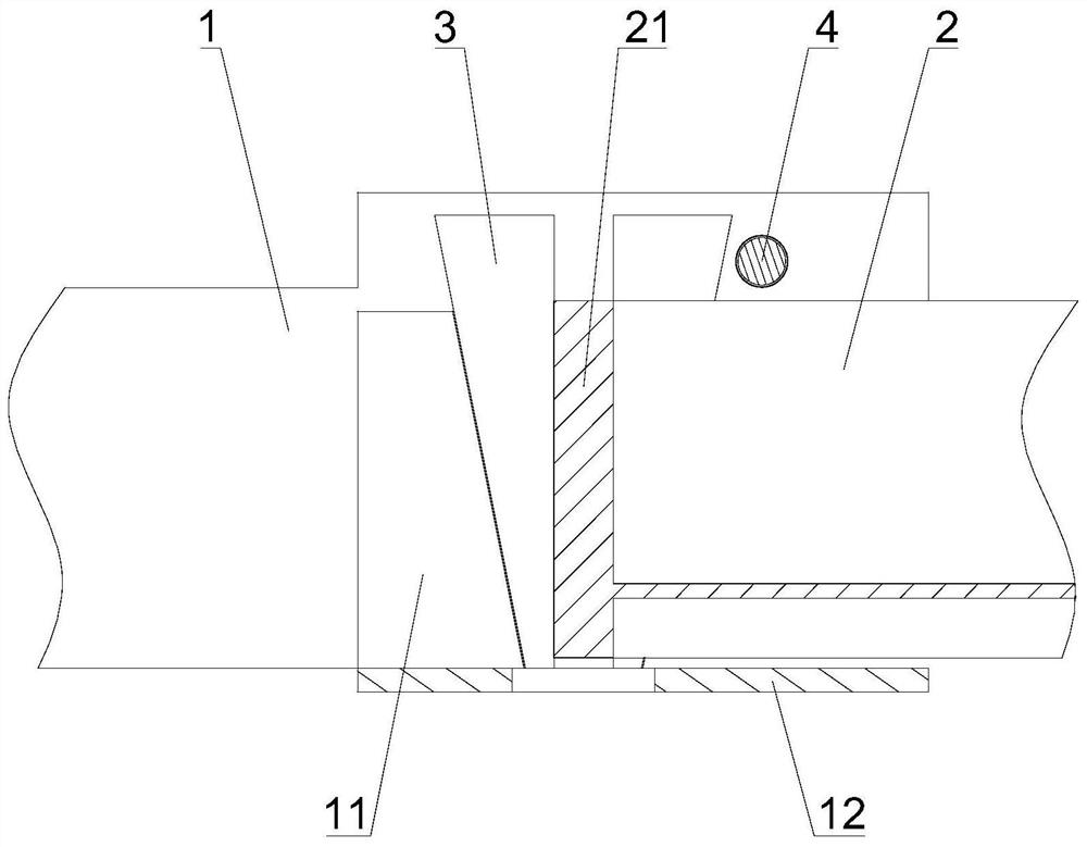
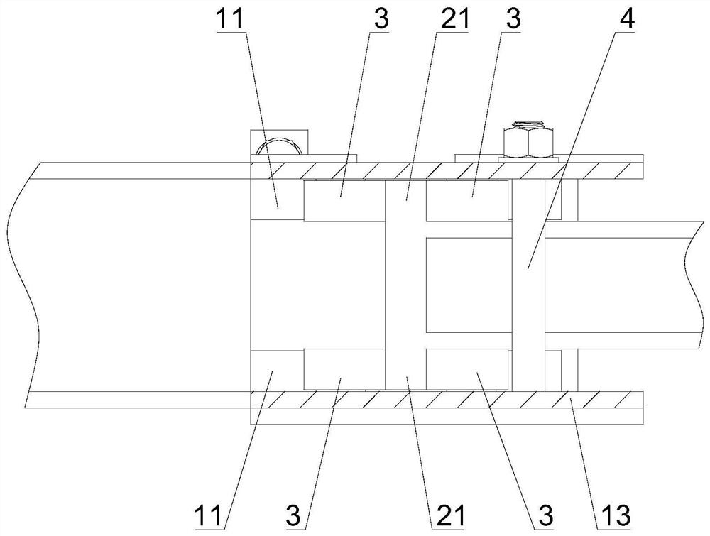
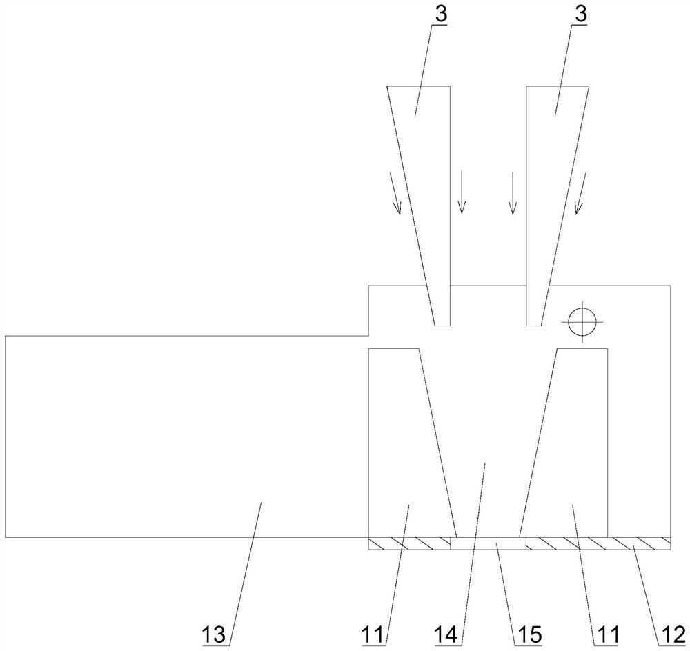
[0027] see Figures 1 to 4 As shown, this embodiment provides a connection structure between an integrated steel profile and a crossbeam, which includes an interface 1 provided on the integrated steel section, a tenon 2 provided at the end of the beam, and a brake iron 3 .

[0028] The edge of the end of the tenon 2 exceeds the side wall of the tenon 2 to form a limit edge 21. Specifically, the tenon 2 includes an I-beam 22 welded on the crossbeam. The end of the I-beam 22 is provided with an end plate 23, and the end plate 23 The edge forms the limiting edge 21 .

[0029] An installation cavity is formed on the interface 1, and two wedge-shaped blocks 11 are respectively arranged on both sides of the installation cavity. Specifically, the interface 1 includes a bottom plate 12 and a side plate 13 ...


PUM


Abstract

The invention discloses a connecting structure and method for integrated profile steel and a cross beam. The connecting structure comprises a connector arranged on the integrated profile steel, a tenon arranged at the end of the cross beam and brake iron, the edge of the end of the tenon exceeds the side wall of the tenon to form a limiting edge, a mounting cavity is formed in the connector, two wedge-shaped blocks are arranged on the two sides of the mounting cavity, the two wedge-shaped blocks are arranged in a spaced mode and form an installation seam gradually narrowing from top to bottom,the tenon is placed into the installation cavity from top to bottom, the limiting edge is embedded into the installation seam, and the brake iron is inserted into a gap between the limiting edge andthe installation seam to fasten the limiting edge. The connecting structure of the integrated structural steel and the cross beam replaces an original connecting mode combined bolt connection and welding, rapid and reliable on-site installation is achieved through splicing and clamping, the connecting gap is reduced, welding operation is omitted, the connecting strength is guaranteed, the on-siteassembly difficulty is lowered, and a new thought is provided for the installation mode of the cross beam. The invention further discloses a connecting method of the integrated profile steel and the cross beam.

Description

technical field [0001] The invention relates to the technical field of integrated profiled steel installation, in particular to a connection structure and connection method between integrated profiled steel and a beam. Background technique [0002] At present, steel structures are used more and more in the field of building structures, and various new forms of steel structures are emerging, which have been applied in the field of engineering, and the number is also rising, with broad prospects. Integrated section steel is a kind of steel structure, especially in the height direction, the tailor welding connection method has great advantages, which reduces the difficulty of on-site construction and improves construction efficiency. [0003] However, when installing a crossbeam between two integrated steel sections on site, the current method is to first connect them with bolts and then weld them into shape. In this method, there are connection gaps in the bolt connection, whi...

Claims


Application Information

Patent Timeline
Patent Type & Authority Applications(China)
IPC IPC(8): E04B1/24E04B1/58E04B1/48
CPCE04B1/2403E04B1/48E04B2001/2409
Inventor 易书云易仕桂陆照俊周越华殷科
Owner WUXI GUANGCAI MACHINERY MFG
Why Eureka
Try Eureka