Cable pay-off rack for electric power construction

A technology for electric power construction and pay-off racks, applied in the direction of conveying filamentous materials, thin material processing, transportation and packaging, etc., can solve the problems of high labor intensity, inconvenient displacement, poor practicability, etc., and achieve a high degree of automation , The effect of reducing labor intensity and improving practicability

Inactive Publication Date: 2021-03-16
湖南金广达电力建设有限公司
View PDF10 Cites 6 Cited by
  • Summary
  • Abstract
  • Description
  • Claims
  • Application Information

AI Technical Summary

Problems solved by technology

[0004] The invention proposes a cable pay-off stand for electric power construction, which solves the problem that the existing cable pay-off stand needs to be manually pulled to realize the cable pay-off, and the manual labor intensity is relatively large; and the existing cable release The wire frame is inconvenient to shift, and the practicability is poor

Method used


Image

  • Cable pay-off rack for electric power construction
  • Cable pay-off rack for electric power construction
  • Cable pay-off rack for electric power construction

Examples


Embodiment Construction

[0024] The following will clearly and completely describe the technical solutions in the embodiments of the present invention with reference to the accompanying drawings in the embodiments of the present invention. Obviously, the described embodiments are only some, not all, embodiments of the present invention.

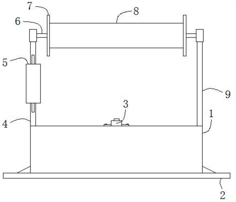
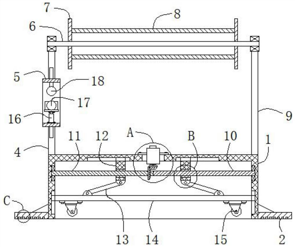
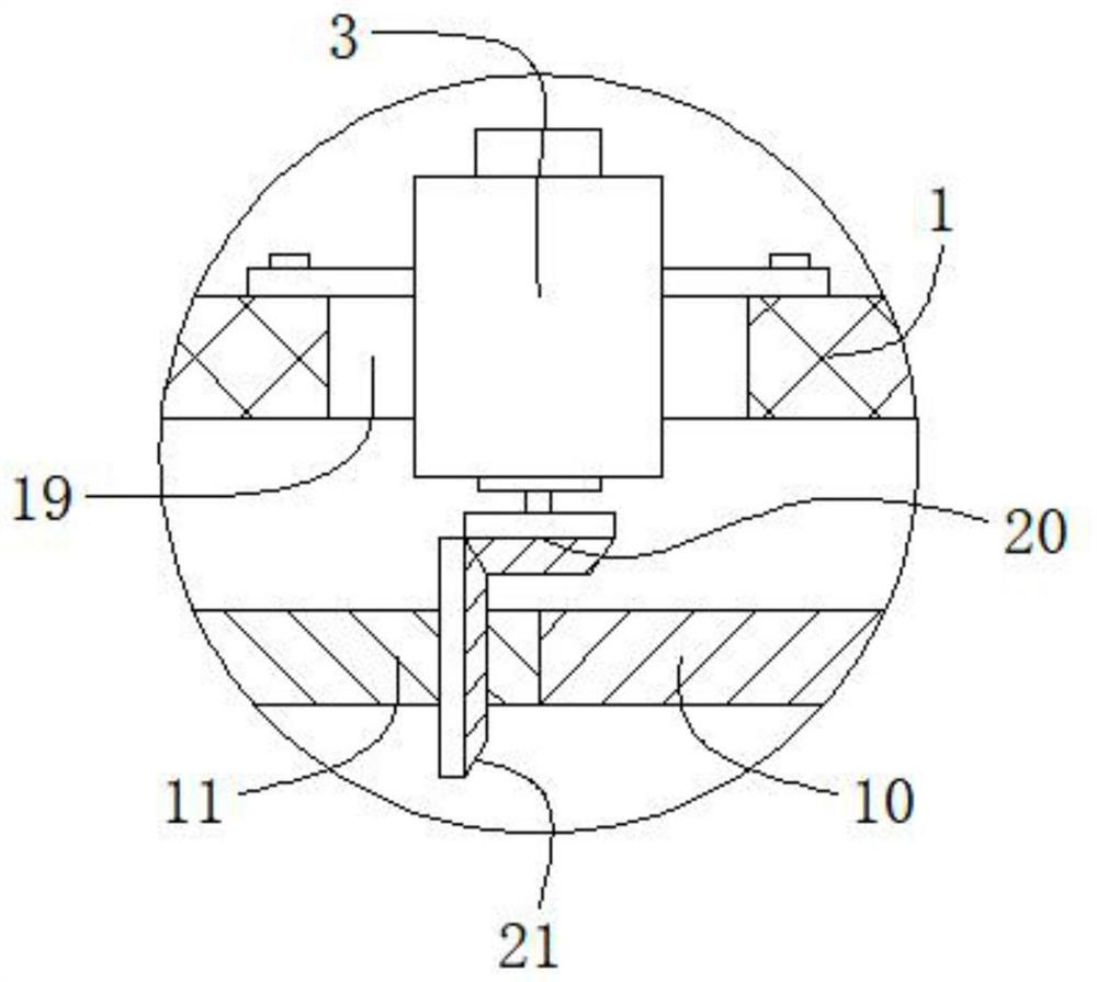
[0025] refer to Figure 1-6 , a cable pay-off frame for electric power construction, comprising a support box 1, the support box 1 has no bottom wall, and the two ends of the outer top wall of the support box 1 are respectively fixed with a vertical first support plate 4 and a vertical second support plate 9. The top of the first support plate 4 is rotatably connected to a horizontal rotating column 6 through a bearing, and the rotating column 6 is rotatably connected to the top of the second support plate 9 through a bearing, and is located between the first support plate 4 and the second support plate 9 The outer rings on both sides of the rotating column 6 are fix...


PUM


Abstract

The invention belongs to the field of electric power construction engineering facilities, and particularly relates to a cable pay-off rack for electric power construction. The cable pay-off rack comprises a supporting box without a bottom wall, a vertical first supporting plate and a vertical second supporting plate are fixed to the two ends of the outer top wall of the supporting box respectively, and the top end of the first supporting plate is rotationally connected with a horizontal rotating column through a bearing. The rotating column is rotatably connected to the top end of the second supporting plate through a bearing, the outer rings of the two sides of the rotating column located between the first supporting plate and the second supporting plate are both fixedly sleeved with vertical limiting plates, a horizontal circular winding drum is fixed between the two limiting plates, the outer ring of the rotating column is sleeved with the winding drum, and a rectangular mounting cylinder which is horizontal is fixed to the position, located at the lower sides of the limiting plates, of the front side end of the first supporting plate. The cable pay-off rack is novel in design,capable of automatically achieving cable pay-off, higher in automation degree, smaller in manual labor intensity, convenient to move, higher in practicability and suitable for application and popularization.

Description

technical field [0001] The invention relates to the technical field of electric power construction engineering facilities, in particular to a cable pay-off rack for electric power construction. Background technique [0002] Electric power engineering refers to engineering related to the production, transmission, and distribution of electric energy. In a broad sense, it also includes engineering that uses electricity as power and energy in various fields. In the process of carrying out electric power construction projects, a large number of cables need to be used, and the cables are usually carried by the cable pay-off frame to facilitate the laying out of the cables. [0003] However, the existing cable pay-off rack needs to be manually pulled to realize the pay-off of the cable, and the labor intensity is relatively large; and the existing cable pay-off rack is inconvenient to shift, and the practicability is poor. We propose a cable pay-off rack for electric power constru...

Claims


Application Information

Patent Timeline
Patent Type & Authority Applications(China)
IPC IPC(8): B65H49/34B65H49/30
CPCB65H49/34B65H49/30B65H2701/34
Inventor 张成才
Owner 湖南金广达电力建设有限公司
Why Eureka
Try Eureka