
An airborne camera back focus anti-loosening locking structure

A camera and lens technology, used in image communication, aircraft parts, televisions, etc., can solve the problems of inconvenient adjustment and complex structure of the focal length locking mechanism, reduce the difficulty of operation, facilitate electromagnetic compatibility, waterproof and good sealing. Effect

Active Publication Date: 2022-08-05
NO 55 INST CHINA ELECTRONIC SCI & TECHNOLOGYGROUP CO LTD
View PDF9 Cites 0 Cited by
  • Summary
  • Abstract
  • Description
  • Claims
  • Application Information

AI Technical Summary

Problems solved by technology

[0007] The purpose of the present invention is to solve the problem of complex structure and inconvenient adjustment of the existing airborne camera focus locking mechanism, and to design a back focus lock lock mechanism for the airborne camera that has a simple and reliable structure, will not loosen after installation and can be self-adaptively adjusted and locked deadlock structure

Method used


Image

  • An airborne camera back focus anti-loosening locking structure
  • An airborne camera back focus anti-loosening locking structure
  • An airborne camera back focus anti-loosening locking structure

Examples


Embodiment Construction

[0022] The present invention will be further described below with reference to the accompanying drawings and embodiments.

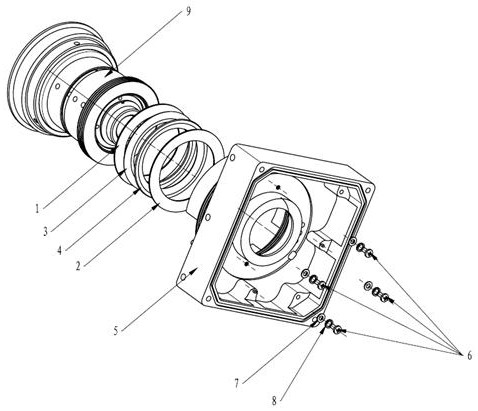
[0023] like figure 1 shown.

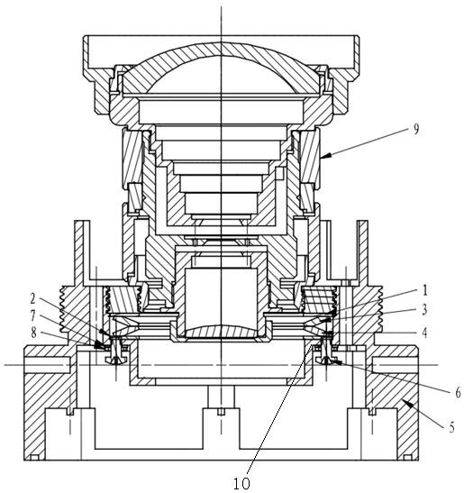
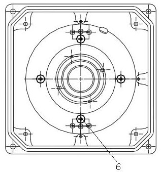
[0024] An airborne camera back focus locking structure, which includes a mesh flat pad 1, a flat pad 2, a first disc spring 3 and a second disc spring 4, such as figure 2 As shown, in the specific implementation, the first disc spring 3 and the second disc spring 4 can also be realized by similar springs or spring assemblies. 2, the mesh flat pad 1, the flat pad 2, the first disc spring 3 and the second disc spring 4 are coaxially installed in the lens mount 5, and the flat pad 2 and the three through the lens mount 5 above( image 3 There are four uniformly distributed cross symmetrical screws 6 against each other, and the cross symmetrical screws 6 are equipped with small flat washers 7 and small spring washers 8. After the cross symmetrical screws 6 pass through the small spring washers 8 and the small flat washers 7 ...


PUM


Abstract

A kind of airborne camera after the carrier camera, the coke anti -pine lock structure is characterized by it includes mesh flat pads (1), flat pads (2), first disk springs (3), and second disk springs (4), first firstAfter the dish spring and the second disk spring are connected in series between the flat pads and flat pads, the mesh flat pads, flat pads, first plate springs, and second disk spring are installed in the lens installation seat (5) in the lens installation seat (5), Flat pads (2) Cross -symmetrical screws (6) with more than 3 cloth installed seats (5) through lens installation seats (5), mesh flat pads (1) thread rotor loop (9) of the camera lens component (9)9‑2) The end surface is offset, and the thread rotor (9‑2) is connected to the inner thread of the inner thread (5) through its external thread, and the lens component (9‑1) of the camera lens component (9)The inner thread of the thread and the thread rotor (9‑2) is connected; it is convenient for installation and disassembly, the plane friction provides locks, and the difficulty of installing and disassembling operations is greatly reduced.

Description

technical field [0001] The invention relates to an airborne technology, in particular to an airborne camera technology, in particular to an airborne camera back focus locking structure. Background technique [0002] At present, aviation airborne cameras require that the focal length will not change under more severe vibration conditions, so that blurred images will not be produced. Although the previous products also have the structure of locking the back focus, but at present, this structure needs to drill holes from the circumferential direction and install the locking screw, which will destroy the thread on which the camera and the threaded adapter ring are installed, and the pressure pits after each adjustment do not overlap. If the screwing depth is difficult to be consistent, the coaxiality of the optical components of the camera will be reduced and the anti-vibration ability will be poor, which will affect the optical accuracy of the camera. This structure has the fo...

Claims


Application Information

Patent Timeline
Patent Type & Authority Patents(China)
IPC IPC(8): H04N5/225B64D47/08
CPCB64D47/08H04N23/54H04N23/50H04N23/55
Inventor 李鹏窦亮岳政军樊卫华陈建军王军义张伟
Owner NO 55 INST CHINA ELECTRONIC SCI & TECHNOLOGYGROUP CO LTD
Learn More