
Filtering-free signal acquisition method, filtering-free signal acquisition system and electric leakage protection device

A technology of signal acquisition and carrier signal, applied in the direction of automatic disconnection emergency protection device, emergency protection circuit device, circuit device, etc., can solve the problems of increasing hardware cost and reducing product reliability, so as to increase reliability and reduce Volume, the effect of saving development and production costs

Active Publication Date: 2021-03-12
GUOCHUANG INNOVATION CENTER OF MOBILE ENERGY (JIANGSU) CO.,LTD.
View PDF4 Cites 1 Cited by
  • Summary
  • Abstract
  • Description
  • Claims
  • Application Information

AI Technical Summary

Problems solved by technology

Building a peripheral hardware filter circuit not only reduces the reliability of the product, increases the hardware cost, but also limits the degree of miniaturization of the product

Method used


Image

  • Filtering-free signal acquisition method, filtering-free signal acquisition system and electric leakage protection device
  • Filtering-free signal acquisition method, filtering-free signal acquisition system and electric leakage protection device
  • Filtering-free signal acquisition method, filtering-free signal acquisition system and electric leakage protection device

Examples


Embodiment 1

[0029] This embodiment provides a filter-free signal acquisition method, including the following steps:

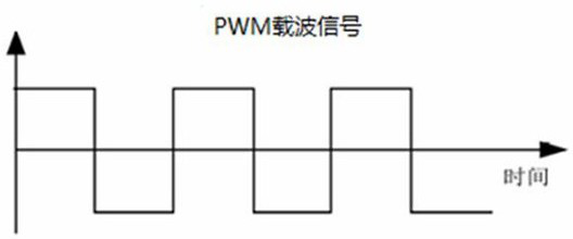
[0030] Step S1: Generate a PWM carrier signal with a frequency of 6KHz through the main control terminal, and output the PWM carrier signal to the modulation signal terminal, where the waveform of the PWM carrier signal is as follows figure 1 shown.

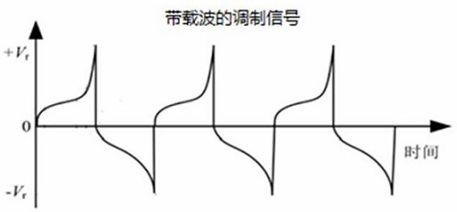
[0031] Step S2: After the modulation signal end receives the PWM carrier signal with a frequency of 6KHz, it modulates the information to be detected, such as leakage signals, etc., onto the PWM carrier signal to form a modulation signal with a carrier, and retransmits it to the main control terminal, where the waveform of the modulated signal with the carrier is shown in figure 2 shown.

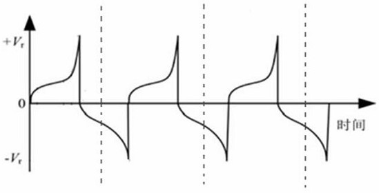
[0032] Step S3: The master control terminal receives the modulated signal with the carrier, and obtains machine N according to the waveform diagram of the modulated signal with the carrier, wherein the N is the time point and the wavefor...

Embodiment 2

[0039]This embodiment provides a leakage protection device, which includes an MCU circuit board, a magnetic core winding, a relay and a leakage signal source arranged in a housing. The relay is connected with the MCU board. The magnetic core winding includes a magnetic core and an N1 winding and an N2 winding wound on the magnetic core, the MCU circuit board is connected to the N1 winding, and the leakage signal source is connected to the N2 winding. The MCU circuit board generates a PWM carrier signal, and transmits the PWM carrier signal to the magnetic core winding. According to the fluxgate principle, the signal output by the N1 winding in the magnetic core winding contains the signal to be collected and the PWM carrier signal, and the reference voltage Vref Modulate this signal to form a modulated signal with a carrier, and send it back to the MCU circuit board. The MCU main control chip on the MCU circuit board directly collects leakage information on the modulated signa...


PUM


Abstract

The invention discloses a filtering-free signal acquisition method, which relates to the technical field of signal acquisition methods, and comprises the following steps that S1, a main control end generates a PWM carrier signal with a certain frequency F, and outputs the PWM carrier signal to a modulation signal end; S2, the modulation signal end modulates information needing to be detected to aPWM carrier signal to form a modulation signal with a carrier, and transmits the modulation signal to the main control end; S3, the main control end obtains N according to the modulation signal oscillogram with the carrier waves; S4, delay time T is calcualted according to a formula T = (1 / F) * N; and S5, the main control end performs ADC sampling on the modulation signal with the carrier at the optimal sampling time point M in each PWM carrier signal period to obtain information needing to be detected. According to the invention, the modulation signal with the carrier wave is collected through the optimal sampling opportunity, the signal does not need to be filtered, the reliability of the product is improved, and the volume of the product is effectively reduced.

Description

technical field [0001] The invention relates to the technical field of signal acquisition methods, in particular to a filter-free signal acquisition method, a system thereof, and a leakage protection device. Background technique [0002] In recent years, signal acquisition technology has been widely used in more and more fields. In traditional signal acquisition technology, before data sampling, the peripheral hardware filter circuit must first be built to filter out the carrier signal, leaving only the baseband signal. Sample the baseband signal. Building a peripheral hardware filter circuit not only reduces the reliability of the product, increases the hardware cost, but also limits the degree of miniaturization of the product. Contents of the invention [0003] The technical problem to be solved by the present invention is to overcome the disadvantages of the prior art and provide a filter-free signal acquisition method, system and leakage protection device. [0004] ...

Claims


Application Information

Patent Timeline
Patent Type & Authority Applications(China)
IPC IPC(8): H02H1/00G01R31/52H02H3/32
CPCH02H1/0007G01R31/52H02H3/32
Inventor 许波周颖杰孟羽
Owner GUOCHUANG INNOVATION CENTER OF MOBILE ENERGY (JIANGSU) CO.,LTD.
Learn More