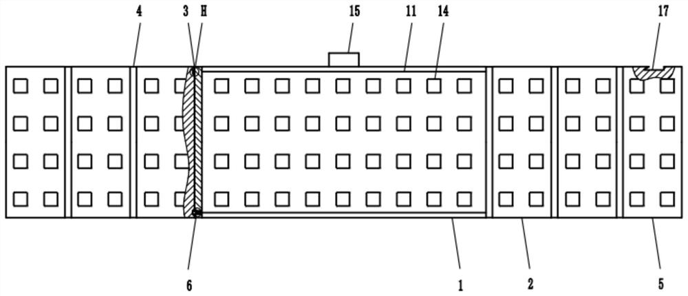
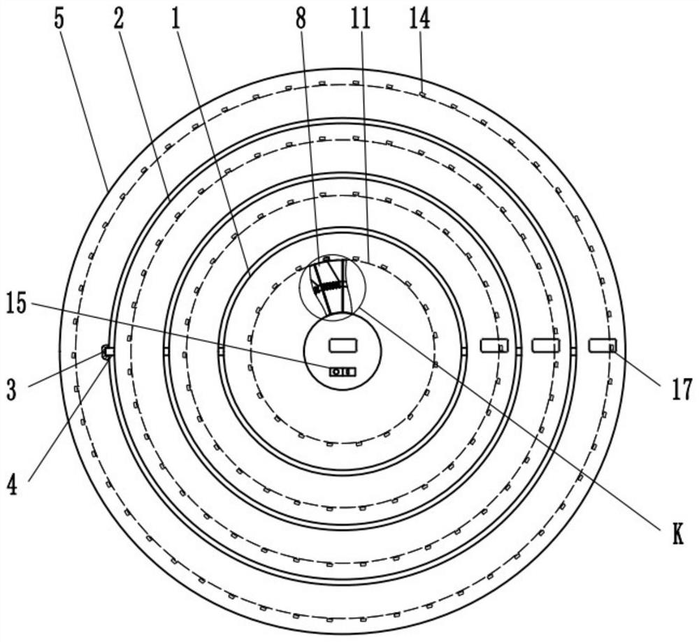
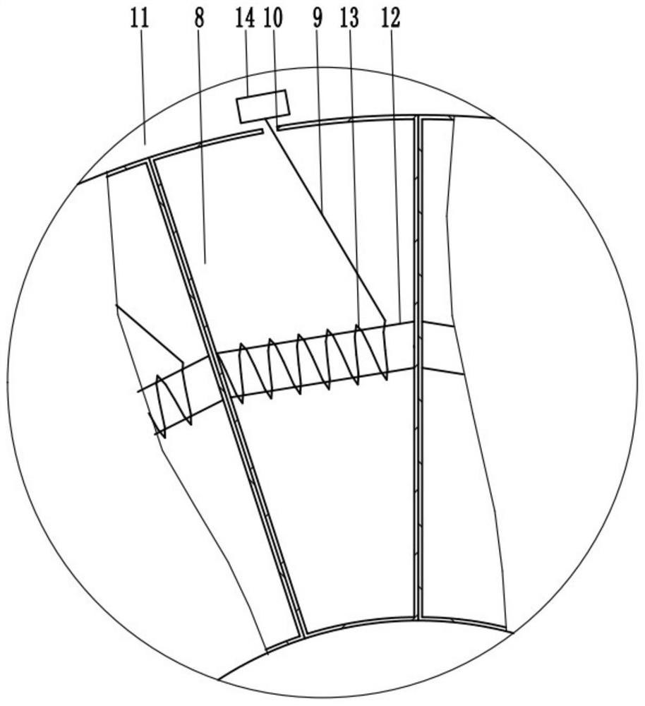
Power grid wiring model for power marketing

A power marketing and power grid technology, applied in teaching models, educational appliances, instruments, etc., can solve the problem of difficult interleaving of multiple lines, and achieve the effects of easy search and positioning, easy storage and portability, and increased use area.

Active Publication Date: 2021-03-12
NANCHANG INST OF TECH
View PDF19 Cites 0 Cited by
  • Summary
  • Abstract
  • Description
  • Claims
  • Application Information

AI Technical Summary

Problems solved by technology

[0003] Power marketers often need to comprehensively consider the wiring of power supply lines to control power supply costs. Now the common method is to draw power supply lines directly on the map with a pen. If a wiring method needs to be designed between two locations, it is necessary to find out the two For all power supply towers between two locations, one wiring may need to be connected sequentially between multiple power supply towers to complete a wiring between two locations, which requires drawing a line connecting multiple power supply towers on the map , in order to calculate the lowest-cost power supply wiring, power marketers need to design a variety of wiring methods during the wiring process, which may result in multiple staggered lines on the map, but this method is ineffective in the face of complex lines. , it is often difficult to compare the wiring method with the lowest cost due to the interleaving of multiple lines

Method used


Image

  • Power grid wiring model for power marketing
  • Power grid wiring model for power marketing
  • Power grid wiring model for power marketing

Examples


Embodiment Construction

[0030] A specific embodiment of the present invention will be described in detail below in conjunction with the accompanying drawings, but it should be understood that the protection scope of the present invention is not limited by the specific embodiment.

[0031] In describing the present invention, it should be understood that the terms "center", "longitudinal", "transverse", "length", "width", "thickness", "upper", "lower", "front", " Rear", "Left", "Right", "Vertical", "Horizontal", "Top", "Bottom", "Inner", "Outer", "Axial", "Radial", "Circumferential" The orientation or positional relationship indicated by etc. is based on the orientation or positional relationship shown in the drawings, and is only for the convenience of describing the technical solution of the present invention and simplifying the description, rather than indicating or implying that the referred device or element must have a specific orientation, Constructed and operative in a particular orientation a...


PUM


Abstract

The invention relates to the technical field of power grid wiring models, and discloses a power grid wiring model for power marketing. The model comprises a wire box, sleeves and an outer cylinder; the wire box is provided with a plurality of wire storage cavities, lines are arranged in the wire storage cavities and can extend out of the outer wall of the wire box from communicating holes in the cavity walls of the wire storage cavities, and the sleeves sequentially sleeve the periphery of the wire box layer by layer; the outer cylinder is sleeved on the periphery of the sleeve on the outermost layer, the inner peripheral walls of the sleeves and the outer cylinder are provided with a plurality of sliding grooves along the axial direction, the sliding grooves penetrate through the upper end faces of the sleeves and the outer cylinder, the outer peripheral walls of the wire box and the sleeve are respectively provided with a plurality of sliding strips along the axial direction, and thesliding strips are in sliding fit with the sliding grooves adjacent to the periphery. Elastic telescopic pieces are arranged on the bottom sides of the sliding strips. The elastic telescopic pieces can extend out of or retract into the outer side walls of the sliding strips in the direction perpendicular to the axial direction of the wire box and are clamped into first grooves, matched with the elastic telescopic pieces, in the groove walls of the top sides of the sliding grooves. The model provided by the invention can conveniently simulate a complex power supply line.

Description

technical field [0001] The invention relates to the technical field of grid wiring models, in particular to a grid wiring model for power marketing. Background technique [0002] Electricity marketing means that in the changing market environment, in order to meet people's power consumption needs, power companies provide power products and corresponding services that meet consumption needs through a series of market-related business activities of power companies, so as to realize the business goals of enterprises. The goal, the essence of power marketing is to adjust the demand level and demand time of the power market, meet the user's reasonable power consumption requirements with good service quality, realize the mutual coordination between power supply and demand, and establish a cooperative partner between power companies and users It encourages users to take the initiative to change their consumption behavior and electricity consumption patterns, improve electricity eff...

Claims


Application Information

Patent Timeline
Patent Type & Authority Applications(China)
IPC IPC(8): G09B23/18
CPCG09B23/188
Inventor 王莉莉
Owner NANCHANG INST OF TECH
Why Eureka
Try Eureka