
Quadrature oscillation simulation device and method for measuring anti-scouring performance of test piece

A technology of orthogonal oscillation and simulation devices, which is applied in the field of orthogonal oscillation simulation devices, can solve the problems of extensiveness, poor experiment reusability, and difficulty in truly reflecting the anti-scourability of materials, etc., to achieve easy manipulation, improved convenience, and improved intuitiveness Effect

Pending Publication Date: 2021-03-12
YULIN UNIV
View PDF0 Cites 0 Cited by
  • Summary
  • Abstract
  • Description
  • Claims
  • Application Information

AI Technical Summary

Problems solved by technology

[0002] At present, the test methods for the anti-erosion performance of materials under the action of orthogonal oscillation are relatively extensive, and the results obtained cannot truly reflect the anti-erosion performance of materials.
Large-scale model experiments consume a lot of financial and material resources in the actual operation process, and the reusability of experiments is poor

Method used


Image

  • Quadrature oscillation simulation device and method for measuring anti-scouring performance of test piece
  • Quadrature oscillation simulation device and method for measuring anti-scouring performance of test piece

Examples


Embodiment 1

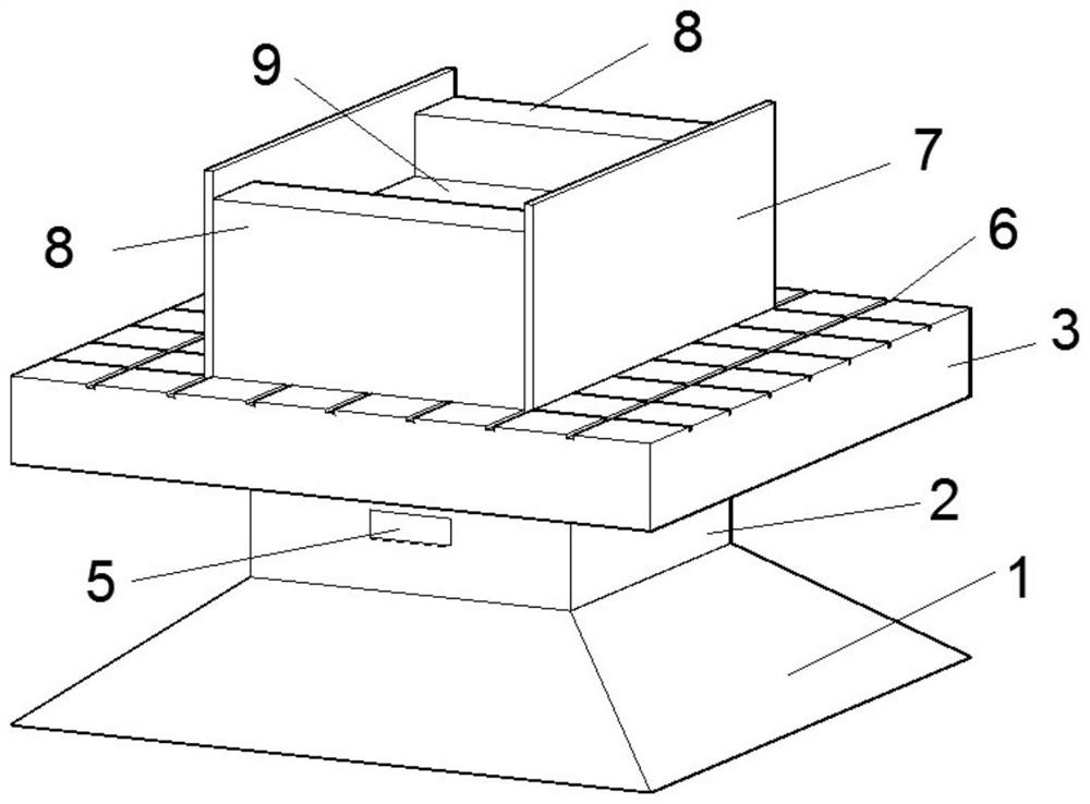
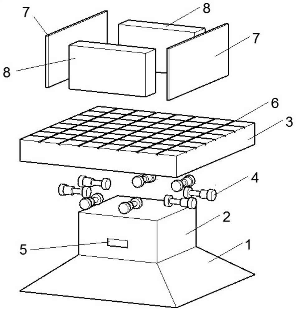
[0030] see figure 1 and figure 2 , a kind of orthogonal oscillation simulation device for measuring the anti-erosion performance of the test piece of the present invention comprises a horizontally arranged base 1, a base 2 is arranged on the base 1, a sliding bottom plate 3 is arranged on the base 2, and the sliding bottom plate 3 8 electric jacks 4 arranged horizontally are installed between the base 2, and the 8 electric jacks 4 are distributed along the orthogonal direction of the horizontal plane. A controller 5 is arranged on the top, and the controller 5 is electrically connected with the electric jack 4 to control the movement of the electric jack 4. The upper surface of the sliding bottom plate 3 is provided with a chute 6, and several chutes 6 are provided. The sliding bottom plate 3 is provided with The baffle 7, the baffle 7 is assembled with the sliding bottom plate 3 through the chute 6, there are 2 to 4 baffles 7, the baffle 7 and the test piece 8 are spliced ​...

Embodiment 2

[0032] This embodiment is the same as Embodiment 1 except for the following content.

[0033] see figure 2 , the sliding bottom plate 3 is assembled with the baffle plate 7 to form a shock assembly, the test piece 8 is fixed by the baffle plate 7, the sliding bottom plate 3 is provided with multi-sized chute 6, and the corresponding baffle plate 7 is selected according to the size of the test piece, so that the baffle plate 7 is assembled with the sliding bottom plate 3 through the chute 6.

Embodiment 3

[0035] This embodiment is the same as Embodiment 1 except for the following content.

[0036] Base 1 and base 2 are rigidly connected and fixed on the experimental platform. Base 2 and sliding bottom plate 3 are connected by electric jack 4. One end of electric jack 4 is connected to base 2 and the other end is connected to sliding bottom plate 3. Orthogonal movement drives the oscillating component to generate horizontal oscillating movement.


PUM


Abstract

The invention discloses a quadrature oscillation simulation device and method for measuring the anti-scouring performance of a test piece, and belongs to the technical field of material tests. Eight electric jacks are controlled by a controller to move; the electric jacks drive an oscillation assembly to perform orthogonal oscillation motion; and therefore, the scouring environment of a material under a real oscillation effect is simulated, the scouring resistance of the material sample under an orthogonal oscillation effect can be visually observed. The test piece is fixed through a baffle, and in the experiment process, the erosion damage process of the test piece under the erosion effect can be visually observed, and therefore, the directness of the device is improved, and the stabilityand the accuracy of the device are ensured.

Description

technical field [0001] The invention belongs to the technical field of material testing, and relates to an orthogonal oscillation simulation device and method for measuring the erosion resistance performance of a test piece. Background technique [0002] At present, the test methods for the anti-erosion performance of materials under the action of orthogonal oscillation are relatively extensive, and the obtained results cannot truly reflect the anti-erosion performance of materials. Large-scale model experiments consume a lot of financial and material resources in the actual operation process, and the reusability of experiments is poor. Contents of the invention [0003] The purpose of the present invention is to overcome the above-mentioned shortcomings in the prior art, and provide an orthogonal oscillation simulation device and method for measuring the anti-scouring performance of a test piece. [0004] In order to achieve the above object, the present invention adopts...

Claims


Application Information

Patent Timeline
Patent Type & Authority Applications(China)
IPC IPC(8): G01N3/56G01N3/02
CPCG01N3/567G01N3/02G01N2203/001
Inventor 韩亚平赵高文穆建勃韩璐
Owner YULIN UNIV
Learn More