
Air conditioner with self-controlled suction temperature

A suction temperature, air conditioner technology, applied in air conditioning systems, space heating and ventilation, heating methods, etc., can solve the problems of compressor reliability decline, unstable performance, etc., to increase the evaporation load and ensure the suction temperature The stability and the effect of ensuring smooth work

Active Publication Date: 2021-11-02
GREE ELECTRIC APPLIANCES INC
View PDF5 Cites 0 Cited by
  • Summary
  • Abstract
  • Description
  • Claims
  • Application Information

AI Technical Summary

Problems solved by technology

During this process, the suction temperature fluctuates violently, which is caused by the incomplete evaporation of the refrigerant in the evaporator. Fluctuations in the suction temperature make the performance of the entire system unstable, and the reliability of the compressor will decrease.

Method used


Image

  • Air conditioner with self-controlled suction temperature
  • Air conditioner with self-controlled suction temperature

Examples


Embodiment Construction

[0032] In order to make the purpose, technical solution and advantages of the present application clearer, the technical solution of the present application will be described in detail below. Apparently, the described embodiments are only some of the embodiments of this application, not all of them. Based on the embodiments in the present application, all other implementation manners obtained by persons of ordinary skill in the art without creative efforts fall within the protection scope of the present application.

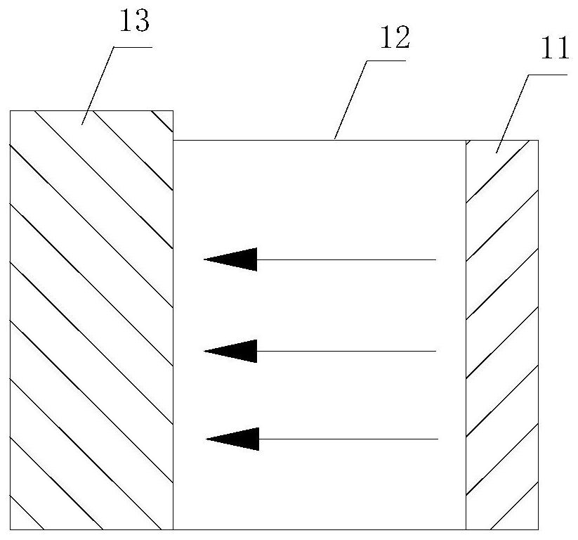
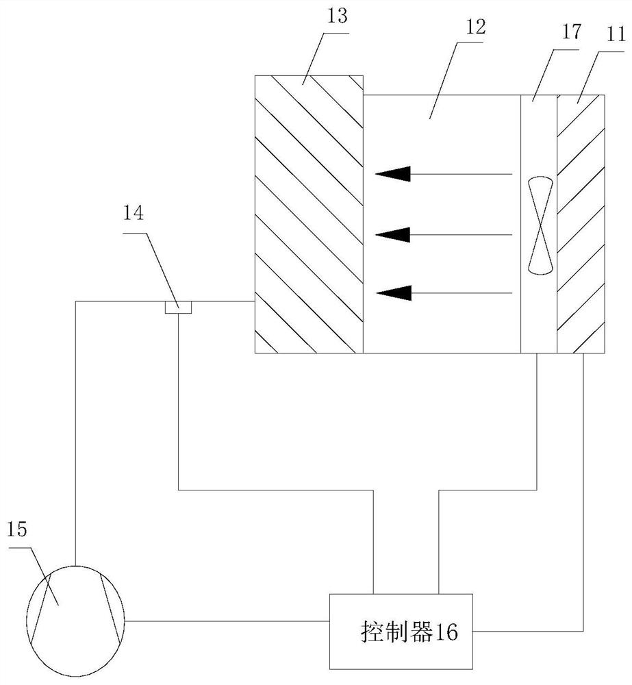
[0033] see figure 1 , figure 1 It is a schematic diagram of the partial structure of an air conditioner with automatic suction temperature control according to an exemplary embodiment, as shown in figure 1 As shown, the air conditioner with automatic suction temperature control includes:

[0034] The auxiliary electric heating device 11 is arranged in the return air channel 12 of the indoor unit of the air conditioner. After the auxiliary electric heating devi...


PUM


Abstract

The application relates to an air conditioner with automatic control of suction temperature, which belongs to the technical field of air conditioners. This application includes: an auxiliary electric heating device, which is arranged in the return air channel of the indoor unit of the air conditioner. After the auxiliary electric heating device heats the return air of the indoor unit of the air conditioner during cooling, the heated return air flows through the evaporator to pass through the air conditioner. Increase the evaporation load of the evaporator to reduce the suction temperature fluctuation. Through this application, it is helpful to ensure the stability of the suction temperature while ensuring the refrigeration, thereby ensuring the stability of the system performance and improving the operation reliability of the air conditioner.

Description

technical field [0001] The application belongs to the technical field of air conditioners, and in particular relates to an air conditioner with automatic control of suction temperature. Background technique [0002] Most of the existing household and commercial air conditioners are based on the working principle of the vapor compression refrigeration cycle, and the refrigeration is performed through the interaction of the evaporator, compressor, condenser and throttling structure. In the actual design process, the factors to be considered are not only the selection of these four components, but also the matching of performance. When performing performance matching, factors to be considered include cooling capacity within a reasonable range, superheat within a reasonable range, and so on. During this process, the suction temperature fluctuates sharply, which is caused by the incomplete evaporation of the refrigerant in the evaporator. The fluctuation of the suction temperatu...

Claims


Application Information

Patent Timeline
Patent Type & Authority Patents(China)
IPC IPC(8): F24F1/0093
CPCF24F2221/34F24F1/0093
Inventor 徐天赐张永伟张磊鹏杨清张棚尹永存
Owner GREE ELECTRIC APPLIANCES INC
Learn More