
Pneumatic holder type butterfly valve

A butterfly valve and clip-type technology, which is applied in the field of pneumatic wafer butterfly valves, can solve the problems of high production cost, large frictional resistance, and large number of pistons, and achieve the effect of low production cost, low frictional resistance, and small number of pistons.

Inactive Publication Date: 2021-03-12
ANHUI TONGDU FLOW TECH
View PDF7 Cites 1 Cited by
  • Summary
  • Abstract
  • Description
  • Claims
  • Application Information

AI Technical Summary

Problems solved by technology

[0003] However, the existing pneumatic wafer butterfly valve driving cylinders are generally single-cylinder double-piston or double-cylinder double-piston, and the shift fork drives the valve shaft to rotate. There are many parts and complex structures. After the appearance of CNC machine tools, there have been disadvantages such as high production costs, uncompact structure, unsightly appearance, inflexible opening and closing, and most of the existing pneumatic wafer butterfly valves lack pressure alarms inside. mechanism, when the internal pressure of the pipeline reaches a high warning pressure, the alarm operation cannot be performed, which will easily cause damage to the pipeline and the valve body, which is not conducive to actual use

Method used


Image

  • Pneumatic holder type butterfly valve
  • Pneumatic holder type butterfly valve
  • Pneumatic holder type butterfly valve

Examples


Embodiment

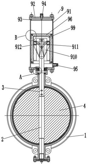
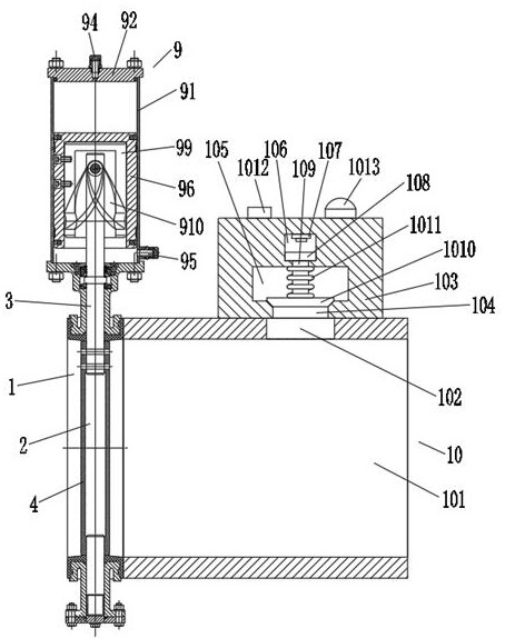
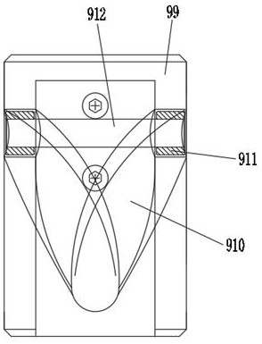
[0025] A pneumatic wafer butterfly valve, comprising a valve body 1, the bottom of the inner wall of the valve body 1 is rotatably connected with a lower valve shaft 2, the top of the lower valve shaft 2 is connected with an upper valve shaft 3 through a connecting pin, and the lower A valve plate 4 is fixedly connected between the valve shaft 2 and the outer side of the upper valve shaft 3, the top of the valve body 1 is fixedly connected with a joint bearing 5, and the top of the upper valve shaft 3 runs through the joint bearing 5 and extends to the valve body 1, the upper valve shaft 3 is fixedly connected with the inner wall of the joint bearing 5, and the upper valve shaft 3 is better connected with the valve body 1 through the joint bearing 5; the top of the valve body 1 is located at the joint bearing 5 is connected with a pressure plate 6 by screws, the top of the upper valve shaft 3 extends to the top of the pressure plate 6, the top of the valve body 1 and the outsid...


PUM


Abstract

The invention discloses a pneumatic holder type butterfly valve which comprises a valve body, wherein the bottom of the inner wall of the valve body is rotatably connected to a lower valve shaft; thetop of the lower valve shaft is connected to an upper valve shaft through a connecting pin. A twisting sleeve twists to drive a rotary rod to rotate, so that the upper valve shaft and the lower valveshaft are driven to rotate, and thus, a valve plate is driven to rotate until linear motion is converted into rotational motion, and opening and closing of the butterfly valve are accomplished; and meanwhile, the volume of a gas cylinder is small, number of pistons is small, friction resistance is small, torque is small, parts are fewer, and opening-closing is flexible; after a numerical-control machine tool appears, the pneumatic holder type butterfly valve has the advantages of being low in production cost, compact in structure, attractive in appearance, and the like; besides, a pressure alarm mechanism can be arranged for detecting pressure inside a pipeline and the valve body; after the pressure reaches a pre-warning value, warning prompt is emitted, so that the pipeline and the valvebody are prevented from being damaged, and thus, actual use is facilitated.

Description

technical field [0001] The invention belongs to the field of butterfly valves, in particular to a pneumatic wafer butterfly valve. Background technique [0002] In the existing life, the butterfly valve is also called the flap valve, which is a regulating valve with simple structure, which can be used for the switch control of the medium in the low-pressure pipeline. There are many types of butterfly valves, and the pneumatic wafer butterfly valve is one of the more common ones. [0003] However, the existing pneumatic wafer butterfly valve driving cylinders are generally single-cylinder double-piston or double-cylinder double-piston, and the shift fork drives the valve shaft to rotate. There are many parts and complex structures. After the appearance of CNC machine tools, there have been disadvantages such as high production costs, uncompact structure, unsightly appearance, inflexible opening and closing, and most of the existing pneumatic wafer butterfly valves lack press...

Claims


Application Information

Patent Timeline
Patent Type & Authority Applications(China)
IPC IPC(8): F16K1/22F16K1/36F16K1/32F16K27/02F16K31/122F16K37/00
CPCF16K1/22F16K1/32F16K1/36F16K27/0218F16K31/122F16K37/0025
Inventor 汪班本
Owner ANHUI TONGDU FLOW TECH
Learn More