Water conservancy and hydropower assembly protection device and using method thereof
A technology for water conservancy and hydropower and protection devices, which is applied in water conservancy projects, coastline protection, marine engineering and other directions, can solve the problems of shortening the service life of the positive and negative motors, large workload of the positive and negative motors, and easy failure of the gate, and achieves reasonable, The effect of reducing workload, improving stability and robustness
- Summary
- Abstract
- Description
- Claims
- Application Information
AI Technical Summary
Problems solved by technology
Method used
Image
Examples
Embodiment 1
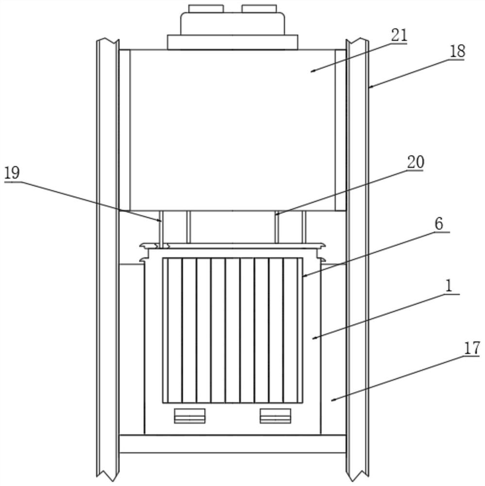
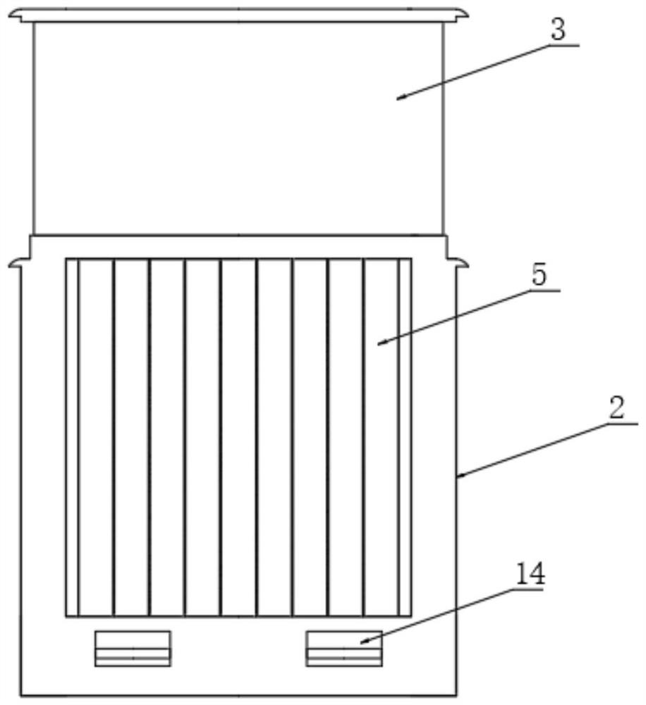
[0041] The present invention provides a protection device for water conservancy and hydropower components, which includes a gate 1 and a protection mechanism installed on the gate 1. The gate 1 includes a first door body 2 and a second door body 3. The first door A cavity 4 is provided inside the body 2, and the second door body 3 is inserted into the cavity 4 and slidably connected with the cavity 4;
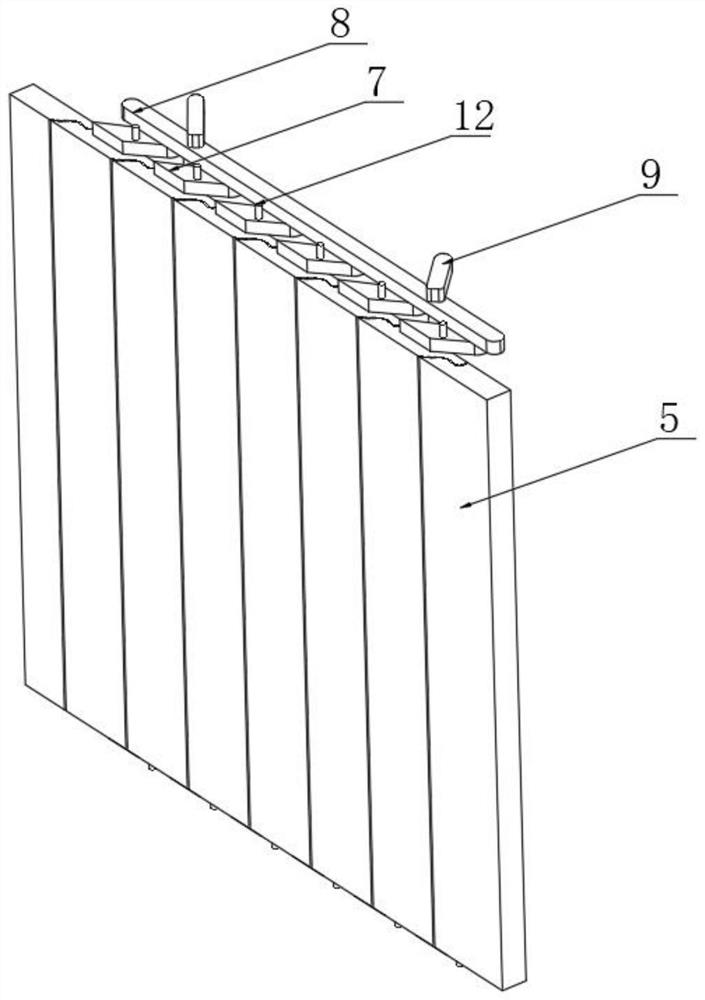
[0042] The protection mechanism includes vertical plates 5 distributed at intervals, and the outer side of the first door body 2 is provided with slots 6 for accommodating the vertical plates 5 , adjacent to the vertical plates 5 are arranged for bonding, and each of the vertical plates 5. Both the top end and the bottom end are fixedly provided with a connecting block 7, the top of the connecting block 7 is hinged with a connecting plate 8, the top of the connecting plate 8 is hinged with a transmission rod 9, and the top of the transmission rod 9 is hinged with a slide rod 10,...
Embodiment 2
[0053] The difference with embodiment 1 is:
[0054] Further, the top of the first door 2 is fixed with a first lifting column 19, the top of the second door 3 is fixed with a second lifting column 20, and a receiving seat 21 is provided directly above the gate 1, so that A storage slot 22 is provided inside the storage base 21 , and two transmission mechanisms are provided on the top of the storage base 21 , and the first lifting column 19 and the second lifting column 20 are connected to the transmission mechanisms through the storage slot 22 .
[0055] Further, the inside of the storage groove 22 is symmetrically provided with a limit mechanism, the limit mechanism includes a limit plate 23, the limit plate 23 is embedded in the storage groove 22 and is slidably connected with the storage groove 22, so One side of the limiting plate 23 is provided with a limiting column 24 at intervals, and the limiting column 24 is slidably arranged in the limiting plate 23, and a compress...
Embodiment 3
[0069] All different from embodiment 1 and embodiment 2:
[0070] Further, the two ends of the vertical plate 5 are provided with interfaces 30, and the adjacent vertical plates 5 are anastomosed and fixed through the interfaces 30, and the inner wall of the interface 30 is bonded with a sealing layer 31, and the sealing layer 31 is set to meet water Expanded rubber seal.
[0071] Specifically, the interface 30 provided on the vertical plate 5 can greatly increase the contact area between adjacent vertical plates 5, improve the stability and firmness of the connection, and the sealing layer 31 at the interface 30 will swell when it encounters water, further Fill the gaps between the risers 5.
[0072] Further, a sealing strip is provided on the surface of the through hole 13 and the guide plate 14, and a buffer layer 32 is provided on the other side of the guide plate 14, and the sealing strip and the buffer layer 32 are both made of rubber material.
[0073] Specifically, t...
PUM
 Abstract
Description
Claims
Application Information
 - R&D
- Intellectual Property
- Life Sciences
- Materials
- Tech Scout
- Unparalleled Data Quality
- Higher Quality Content
- 60% Fewer Hallucinations
Browse by: Latest US Patents, China's latest patents, Technical Efficacy Thesaurus, Application Domain, Technology Topic, Popular Technical Reports.
© 2025 PatSnap. All rights reserved.Legal|Privacy policy|Modern Slavery Act Transparency Statement|Sitemap|About US| Contact US: help@patsnap.com


