
Textile machine with yarn roll reverse rotation driving device

A technology of textile machinery and driving device, which is applied to the field of textile machinery with a yarn roll reversing driving device, can solve the problems of manpower and material resources, complicated control, poor safety, etc., and achieves the effect of reducing learning cost and simple operation and control.

Inactive Publication Date: 2021-03-12
温州邑品鞋业有限公司
View PDF1 Cites 0 Cited by
  • Summary
  • Abstract
  • Description
  • Claims
  • Application Information

AI Technical Summary

Problems solved by technology

[0005] The object of the present invention is to provide a textile machine with a reversing driving device for yarn rolls, so as to solve the problem that the existing prevention machines proposed in the background technology usually need to be manually lifted to install and disassemble the yarn rolls, which is very labor-intensive. Material resources lead to a relatively large workload for the operator. At the same time, the heavy yarn roll is easy for the operator to be injured when handling it, and the safety is poor. At the same time, after the existing yarn roll breaks, the operator manually reverses the yarn roll from the yarn roll. It is time-consuming and labor-intensive to find the head of the yarn; the reversing device requires multiple sets of gears to reverse, the control is more complicated, it is not easy to maintain, and the learning cost is relatively high.

Method used


Image

  • Textile machine with yarn roll reverse rotation driving device
  • Textile machine with yarn roll reverse rotation driving device
  • Textile machine with yarn roll reverse rotation driving device

Examples


Embodiment Construction

[0028] The following will clearly and completely describe the technical solutions in the embodiments of the present invention with reference to the accompanying drawings in the embodiments of the present invention. Obviously, the described embodiments are only some, not all, embodiments of the present invention.

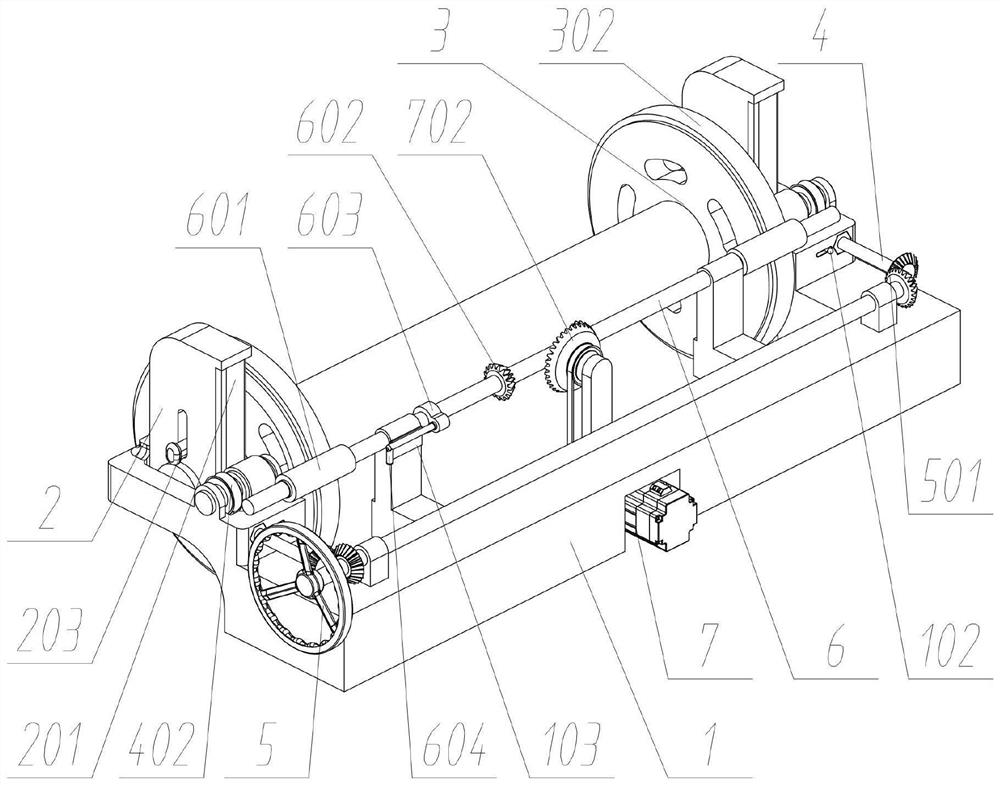
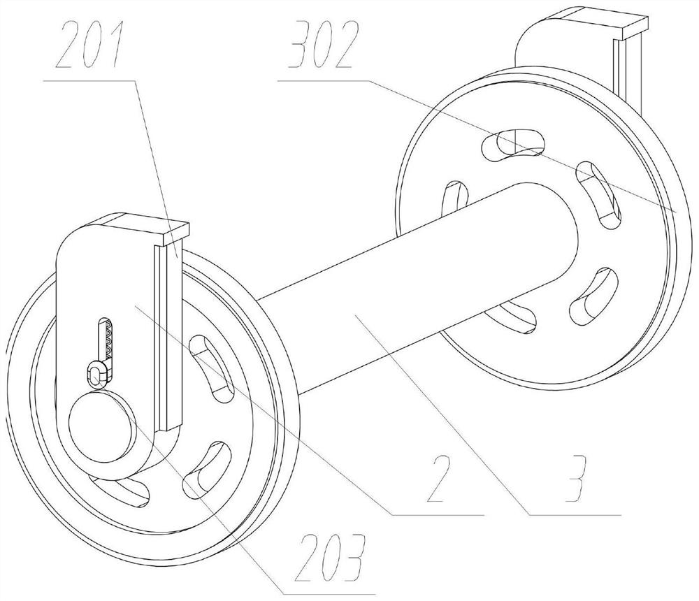
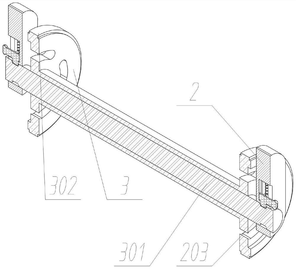
[0029] see Figure 1 to Figure 10 , an embodiment provided by the present invention: a textile machine with a yarn roll reversing drive device, including a yarn roll support 1; two sets of yarn roll lifters 2 are slidingly connected to the front of the yarn roll support 1, and each set of yarn rolls lifts A group of lifting rack racks 201 are fixedly connected to the rear of the frame 2; a group of yarn rolling rollers 3 are rotatably connected to the inside of the yarn rolling lifting frame 2, and a group of yarn rolling gears 302 are respectively fixedly connected to the outer ends of the yarn rolling rollers 3; The two sides of each set of elevator bevel gears 4 a...


PUM


Abstract

The invention discloses a textile machine with a yarn roll reverse rotation driving device, and relates to the technical field of textile machines. The textile machine aims to solve the problems thatan existing textile machine usually requires manual mounting and dismounting of a yarn roll, and consequently the workload of an operator is large; and the yarn roll is manually inverted after being broken, time and labor are wasted, and the learning cost is high. According to the textile machine, two yarn roll lifting frames are slidably connected to the front portion of a yarn roll support; a yarn roller is rotationally connected between the yarn roll lifting frames; a lifting frame bevel gear is rotationally connected to each of the two sides of the yarn roll support; a lifting frame operation rod is transversely and rotationally connected into the yarn roll support; and a yarn roll transmission rod is slidably connected into the yarn roll support. A yarn roll is mounted and dismountedthrough lifting frame gears, so that the textile machine saves more physical strength and is more user-friendly; and forward rotation and reverse rotation of the yarn roller are realized through a reverse rotation control rod, the rotation direction of a motor does not need to be changed, operation control is simpler, and the learning cost of operators is reduced.

Description

technical field [0001] The invention relates to the technical field of textile machinery, in particular to a textile machinery with a yarn roll reversing driving device. Background technique [0002] Textile machine is the full name of a tool that processes raw materials such as thread, silk, and hemp into silk and then weaves them into cloth. The fibers used in textiles in various countries are natural fibers, generally three short fibers of wool, hemp, and cotton. Existing textile machinery It usually includes several rows of identical spinning stations arranged side by side, and a spinning unit for processing yarn is set at the lower part of each spinning station, and the yarn may be broken due to various reasons during the spinning process , due to the inertial rotation of the yarn roll, the operator manually reverses the yarn roll to find the head of the yarn from the yarn roll, and then leads the broken yarn to the spinning unit for splicing. [0003] For example, the...

Claims


Application Information

Patent Timeline
Patent Type & Authority Applications(China)
IPC IPC(8): B65H75/38B65H75/44
CPCB65H75/38B65H75/4457B65H75/4481B65H75/4486B65H2701/174B65H2701/31
Inventor 李秋琼龚华
Owner 温州邑品鞋业有限公司
Learn More