
Undercarriage control system and method for unmanned aerial vehicle

A control system and landing gear technology, applied in the field of unmanned aerial vehicles, can solve problems such as low safety, and achieve the effect of speeding up the flight speed, improving the control method, and reducing the longitudinal height

Active Publication Date: 2021-03-12
重庆空翼航天科技有限公司
View PDF9 Cites 1 Cited by
  • Summary
  • Abstract
  • Description
  • Claims
  • Application Information

AI Technical Summary

Problems solved by technology

[0006] The present invention aims to provide a landing gear control system and method for unmanned aerial vehicles, which can solve the problem of low safety

Method used


Image

  • Undercarriage control system and method for unmanned aerial vehicle
  • Undercarriage control system and method for unmanned aerial vehicle
  • Undercarriage control system and method for unmanned aerial vehicle

Examples


Embodiment 1

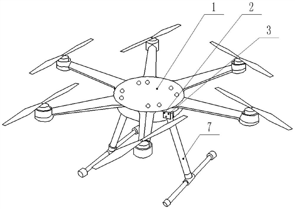
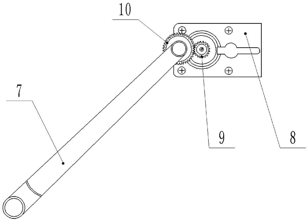
[0051] Such as Figure 1-3 As shown, the landing gear control system for UAV, including:

[0052]The body 1, the bottom of the body 1 is fixed with a connecting piece, the connecting piece includes two supporting plates 2 arranged at intervals, and a plurality of first through holes 3 are provided on the two supporting plates 2;

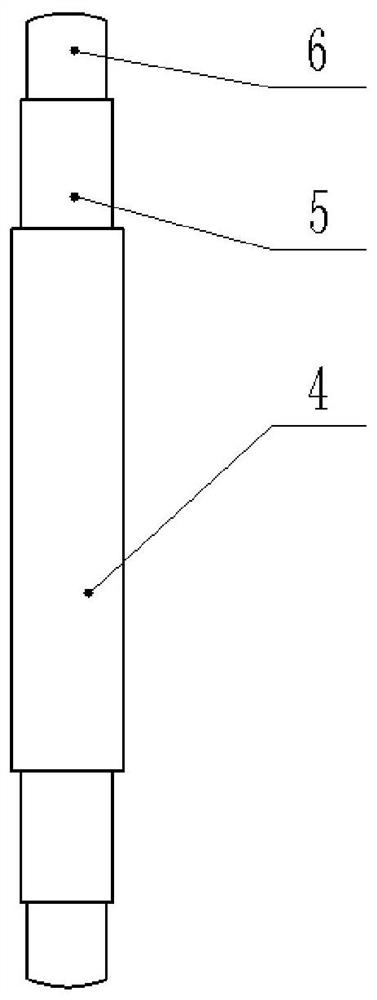
[0053] The locking part, the locking part includes a sleeve 4, two sleeves 5, two pressing caps 6 and a spring, the two sleeves 5 are respectively fixed on the left and right ends of the sleeve 4, and the pressing cap 6 and the sleeve 5 are threaded Connection; that is, the sleeve 5 is provided with internal threads, and the outer surface of the pressing cap 6 is provided with external threads; and, in order to facilitate the user to rotate the pressing cap 6, the end of the pressing cap 6 away from the sleeve 5 is an inner hexagonal nut. What the spring adopts is a helical spring, which is located in the casing 4, and the two ends of the spring are...

Embodiment 2

[0068] Compared with Embodiment 1, the only difference is that it also includes a user terminal (mobile phone); the processing module is also used to generate a warning message (please put down the landing gear 7 when the drone lands) while generating the control command; The input module is also used to send alarm information to the user terminal;

[0069] In the method for controlling the landing gear 7 of the unmanned aerial vehicle, on the basis of the first embodiment, step S4 specifically includes step S41 of generating a control command and sending warning information to the user terminal.

Embodiment 3

[0071] Compared with Embodiment 1, the only difference is that a camera is fixed on the drone body, and a remote controller for controlling the drone is also included; a mobile phone holder is arranged on the remote controller, and a mobile phone terminal is fixed on the mobile phone holder. The mobile terminal is used to obtain video images captured by the camera. The mobile phone also includes a front-facing camera, which is used to obtain the user’s posture image; the processing module is also used to judge the user’s posture image when the drone’s movement direction is downward. If the user’s gaze focus in the posture image is on the mobile phone above, it is judged that the UAV is flying at a low altitude; on the contrary, if the user’s posture is looking forward, it is judged that the UAV is landing; it also includes a self-correction module, which is used for the preset time, if there is a gaze forward posture and a gaze For the user attitude of the mobile phone, the cu...


PUM


Abstract

The invention relates to the technical field of unmanned aerial vehicles, in particular to an undercarriage control system and a method for an unmanned aerial vehicle. The system comprises an aerial vehicle body, a locking part, an undercarriage, and an electric assembly; and also comprises a controller, an acceleration sensor and a distance measuring sensor which are fixedly arranged in the aerial vehicle body, the acceleration sensor and the distance measuring sensor are in signal connection with the controller, and the controller is in signal connection with a steering engine; the controller comprises an input module used for obtaining the running direction collected by the acceleration sensor and receiving the ground clearance collected by the distance measuring sensor; a processing module which is used for detecting the moving direction of the unmanned aerial vehicle, judging whether the ground clearance is smaller than a preset height threshold value or not when the moving direction is downward, and generating a control instruction if the ground clearance is smaller than the preset height threshold value and the unmanned aerial vehicle does not put down the undercarriage; andan output module which is used for receiving the control instruction and driving the steering engine to put down the undercarriage according to the control instruction; by adopting the scheme, the problem of low safety can be solved.

Description

technical field [0001] The invention relates to the technical field of unmanned aerial vehicles, in particular to a landing gear control system and method for unmanned aerial vehicles. Background technique [0002] With the development of science and technology, UAVs have broad application prospects due to their outstanding mission performance, lower energy consumption and zero casualties. Generally speaking, UAVs are equipped with landing gear for supporting the body, so that the UAV can stand and support through its landing gear when it lands. In order to prevent the landing gear fixed on the body from being unable to retract and retract, which would affect the operation of the UAV, the existing UAV is equipped with a retractable landing gear function. [0003] For example, Chinese Patent Publication No. CN207697992U discloses a multi-rotor unmanned aerial vehicle landing gear folding retractable device, including landing gear support, steering gear bracket, steering gear...

Claims


Application Information

Patent Timeline
Patent Type & Authority Applications(China)
IPC IPC(8): B64C25/00B64C25/10B64C25/24B64C25/26B64C27/08G08B21/24
CPCB64C25/001B64C25/10B64C25/24B64C25/26B64C27/08G08B21/24B64U10/10
Inventor 郑均
Owner 重庆空翼航天科技有限公司
Learn More