Self-locking mechanism and self-locking joint planer

A self-locking and rotating sleeve technology, used in medical science, surgery, etc., can solve the problems of low tool disassembly and assembly, complex installation and fixation structure, etc., achieve high surgical efficiency and accuracy, simplify installation and fixation structure, and improve disassembly and assembly. The effect of efficiency

Pending Publication Date: 2021-03-12
STAR SPORTS MEDICINE CO LTD
View PDF0 Cites 4 Cited by
  • Summary
  • Abstract
  • Description
  • Claims
  • Application Information

AI Technical Summary

Problems solved by technology

[0004] For medical operations where every second counts and efficiency is emphasized, the above-mentioned knives are inefficient in disassembly and assembly due to the complicated installation and fixing structure.

Method used


Image

  • Self-locking mechanism and self-locking joint planer
  • Self-locking mechanism and self-locking joint planer
  • Self-locking mechanism and self-locking joint planer

Examples


no. 1 example

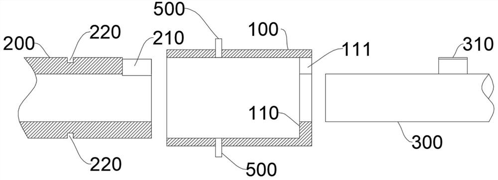
[0037] figure 1 It is a schematic exploded view of the structure of the self-locking mechanism provided by the first embodiment of the present invention; figure 2 An exploded cross-sectional view of the structure of the self-locking mechanism provided by the first embodiment of the present invention; image 3 It is a structural sectional view of the self-locking mechanism provided by the first embodiment of the present invention. Please refer to figure 1 , figure 2 , image 3 , the present embodiment provides a self-locking mechanism, which includes a rotating sleeve 100 , a connecting cylinder 200 and a connecting column 300 that are sequentially nested from outside to inside.

[0038] Wherein, the inner wall of the rotating sleeve 100 is provided with a limiting ring platform 110, and the first end face of the connecting cylinder 200 faces the limiting ring platform 110; the first end surface is provided with a first notch 210, and the limiting ring platform 110 is provi...

no. 2 example

[0049] Figure 4 It is a schematic exploded view of the structure of the self-locking mechanism provided by the second embodiment of the present invention; Figure 5 An exploded cross-sectional view of the structure of the self-locking mechanism provided by the second embodiment of the present invention; Image 6 It is a cross-sectional view of the relevant structure of the clockwork spring 420 in the self-locking mechanism provided by the second embodiment of the present invention. Please refer to Figure 4 , Figure 5 , Image 6 , the present embodiment provides a self-locking mechanism, which is substantially the same as the self-locking mechanism of the first embodiment, the difference between the two is that the elastic member in the self-locking mechanism of the present embodiment includes a clockwork spring 420; the clockwork spring 420 The inner end of the clockwork spring 420 is fixed on the connecting cylinder 200 , and the outer end of the clockwork spring 420 i...

no. 3 example

[0057] Figure 7 It is a sectional view of the structure of the self-locking joint planer provided by the third embodiment of the present invention. Please refer to Figure 7 , this embodiment provides a self-locking joint planer, which includes a handle 600, a cutter head 700 and the self-locking mechanism of any of the above embodiments, the connecting cylinder 200 is arranged on the handle 600, and the cutter head 700 is arranged on Connection column 300.

[0058] Further, as Figure 7 As shown, the axis of the cutter head 700 coincides with the axis of the connecting post 300 .


PUM


Abstract

The invention provides a self-locking mechanism, and relates to the technical field of medical tools. The self-locking mechanism comprises a rotating sleeve, a connecting cylinder and a connecting column which are sequentially connected in a sleeved mode from outside to inside. A limiting ring table is arranged on the inner wall of the rotating sleeve, and the first end face of the connecting cylinder faces the limiting ring table; a first notch is formed in the first end face, and a second notch is formed in the limiting ring table; a limiting protruding block is arranged on the annular faceof the connecting column. An elastic piece and a retaining device are arranged between the rotating sleeve and the connecting cylinder, the elastic piece is used for driving the rotating sleeve to rotate relative to the connecting cylinder, and the retaining device is used for limiting the rotating sleeve to move relative to the connecting cylinder in the axis direction of the rotating sleeve. According to the self-locking mechanism, the three structures of the rotating sleeve, the connecting cylinder and the connecting column, the elastic piece and the retaining device are utilized, and the problem that the tool bit is inconvenient to mount and dismount is solved through relative rotating and moving operation of the components. On the basis, the invention further provides a self-locking type joint planing device.

Description

technical field [0001] The invention relates to the technical field of medical knives, in particular to a self-locking mechanism and a self-locking joint planer. Background technique [0002] It is often necessary to cut and repair diseased joint tissue in medical operations, and the instrument used in this operation is a joint planer. [0003] In order to fix and install the tool, the joint planer in the prior art generally uses fastening screws to screw the tool to the handle, or the tool is encased and screwed to the handle through a sleeve with internal threads. . [0004] For medical operations where every second counts and efficiency is emphasized, the above-mentioned knives are inefficient in disassembling and assembling the knives due to the complicated installation and fixing structure. Contents of the invention [0005] The object of the present invention is to provide a self-locking mechanism and a self-locking joint planer, which help to solve the above techn...

Claims


Application Information

Patent Timeline
IPC IPC(8): A61B17/16
CPCA61B17/1659A61B17/162
Inventor 董文兴赵虎徐栋
Owner STAR SPORTS MEDICINE CO LTD
Why Eureka
Try Eureka