Engine cooling system and control method thereof

A technology of engine cooling and control method, which is applied in the direction of engine cooling, coolant flow control, cooling device control device, etc., and can solve problems such as reducing engine warm-up speed, engine temperature rise loss, and affecting engine warm-up speed , to achieve the effect of reducing temperature rise loss and increasing warm-up speed

Inactive Publication Date: 2021-03-09
DONGFENG MOTOR CORP HUBEI
View PDF15 Cites 0 Cited by
  • Summary
  • Abstract
  • Description
  • Claims
  • Application Information

AI Technical Summary

Problems solved by technology

However, in the process of starting the engine at low temperature, although the temperature control valve is not opened, the coolant flowing out of the engine degassing pipeline forms an external cooling circuit through the radiator degassing pipeline, radiator, and engine water inlet pipe, thus reducing the engine warm-up. speed, which affects the temperature rise rate of the air conditioner in the passenger compartment; and during the warm-up phase of the engine, the temperature rise of the engine will be dissipated into the radiator through the coolant in the form of heat radiation, causing the temperature rise loss of the engine during the warm-up phase, thus affecting the engine temperature. warm-up speed

Method used


Image

  • Engine cooling system and control method thereof
  • Engine cooling system and control method thereof
  • Engine cooling system and control method thereof

Examples


Embodiment Construction

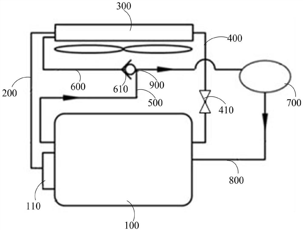
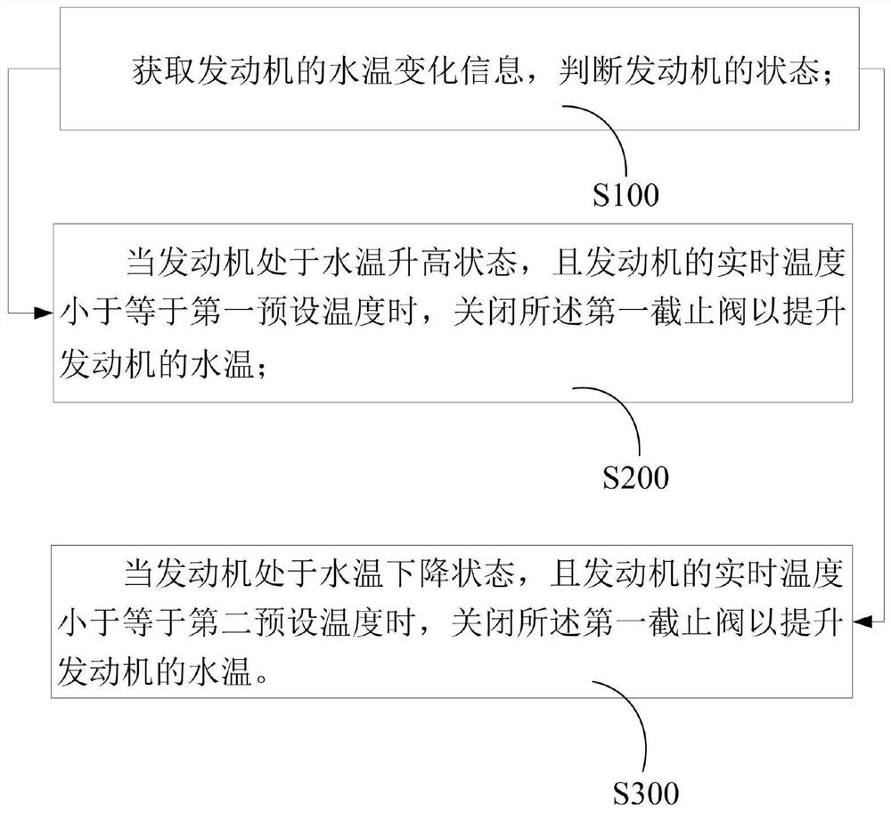
[0037] Reference will now be made in detail to specific embodiments of the invention, examples of which are illustrated in the accompanying drawings. While the invention will be described in conjunction with specific embodiments, it will be understood that it is not intended to limit the invention to the described embodiments. On the contrary, it is intended to cover alterations, modifications and equivalents as included within the spirit and scope of the invention as defined by the appended claims. It should be noted that the method steps described here can all be realized by any functional block or functional arrangement, and any functional block or functional arrangement can be realized as a physical entity or a logical entity, or a combination of both.

[0038] In order to enable those skilled in the art to better understand the present invention, the present invention will be further described in detail below in conjunction with the accompanying drawings and specific embo...


PUM


Abstract

The invention relates to an engine cooling system and a control method thereof. The engine cooling system comprises an engine heat dissipation mechanism and an engine degassing mechanism, wherein theengine heat dissipation mechanism comprises a temperature control valve, an engine water outlet pipeline connected with the temperature control valve, a radiator assembly connected with the engine water outlet pipeline, and an engine water inlet pipeline connected with the radiator assembly; the engine degassing mechanism comprises an engine degassing pipeline, a degassing chamber assembly connected with the engine degassing pipeline, a degassing chamber water outlet pipeline connected with the degassing chamber assembly, and a radiator degassing pipeline connected with a water inlet of the radiator assembly and the degassing chamber assembly; the radiator degassing pipeline is connected with the engine degassing pipeline through a three-way valve; a first stop valve is arranged on the engine water inlet pipeline; and a control valve for preventing reverse flow is arranged on the radiator degassing pipeline. By means of the engine cooling system and the control method thereof, the engine warming speed of an engine can be increased in the low-temperature starting process of the engine and the engine warming stage of the engine.

Description

technical field [0001] The invention relates to the technical field of engines, in particular to an engine cooling system and a control method thereof. Background technique [0002] At present, the engine cooling system adopts the engine water outlet temperature control valve scheme to replace the engine water inlet thermostat scheme. Without changing the structure of the existing degassing chamber, the engine degassing pipeline is degassed by adding a tee to the radiator degassing pipeline. The gas pipeline is connected to the tee to realize the need to discharge the gas in the cooling circuit through the engine degassing pipeline during engine operation, so as to reduce the risk of cavitation and improve the life of the engine. However, in the process of starting the engine at low temperature, although the temperature control valve is not opened, the coolant flowing out of the engine degassing pipeline forms an external cooling circuit through the radiator degassing pipeli...

Claims


Application Information

Patent Timeline
IPC IPC(8): F01P3/20F01P11/02F01P7/16
CPCF01P3/20F01P7/165F01P11/028F01P2007/146F01P2037/02
Inventor 万嘉明刘志同陈志勇王乐万鑫
Owner DONGFENG MOTOR CORP HUBEI
Why Eureka
Try Eureka