Automatic pallet feeding device and method thereof

A pallet and automatic technology, applied in the direction of conveyor control devices, transportation and packaging, conveyor objects, etc., can solve the problems of potential safety hazards, time-consuming and labor-intensive problems, and achieve the effect of reducing potential safety hazards

Pending Publication Date: 2021-03-09
CHINA NAT HEAVY MACHINERY RES INSTCO
View PDF6 Cites 1 Cited by
  • Summary
  • Abstract
  • Description
  • Claims
  • Application Information

AI Technical Summary

Problems solved by technology

In the process of loading wooden pallets on the existing metal plate packaging line, the wooden pallets are usually placed on the ground outside the packaging line, and the metal plates are manually lifted onto the wooden pallets. This method needs to occupy the already busy crane in the workshop. Time-consuming and labor-intensive, and there are security risks

Method used


Image

  • Automatic pallet feeding device and method thereof
  • Automatic pallet feeding device and method thereof
  • Automatic pallet feeding device and method thereof

Examples


Embodiment 1

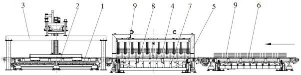
[0034] refer to figure 1 and figure 2 , the embodiment of the present invention proposes an automatic pallet loading device, including: pallet conveying roller 1, pallet conveying chain 2, plate stack clamping position conveying chain 4, entrance conveying chain 6 and control system; one end of pallet conveying chain 2 Opposite to one side of the pallet conveying roller table 1, a pallet lifting mechanism 3 is arranged between the pallet conveying roller table 1 and the pallet conveying chain 2; one end of the pallet conveying chain 4 is opposite to one end of the pallet conveying chain 2 , the upper part of the conveying chain 4 at the plate stack clamping position is provided with a plate stack clamping mechanism 5; the inlet conveyor chain 6 is docked at the other end of the conveying chain 4 at the plate stack clamping position; the signal output end of the control system is respectively connected with the pallet conveying chain 2 , The pallet lifting mechanism 3, the bo...

Embodiment 2

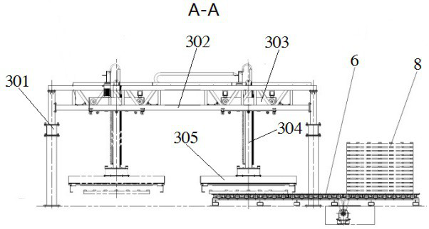
[0040] refer to image 3 and Figure 4 On the basis of Embodiment 1, the pallet lifting mechanism 3 includes: a pair of bridge frames 301, a pair of rail beams 302, and a traverse trolley 303; The two ends of the two track beams 302 are fixedly connected to the two bridge frames 301 respectively; the two sides of the traverse trolley 303 are rolled and assembled on the two track beams 302 respectively, and the traverse trolley 303 is provided with a lifting mechanism 304 and Grab mechanism 305 .

[0041] The traverse trolley 303 is driven by a motor, and the traverse trolley 303 is provided with a working position proximity switch and a lifting position proximity switch. The lifting upper limit switch, the lower lifting limit switch and the wire encoder on the pallet lifting mechanism 3 are all set in the lifting mechanism. 304 on.

Embodiment 3

[0043] refer to image 3 and Figure 4 On the basis of Embodiment 3, the lifting mechanism 304 includes a vertical column 306 and a lifting motor 307, the vertical column 306 is vertically slidably assembled on the traverse trolley 303, and one side of the vertical column 306 is provided with a rack 311, A gear is connected to the main shaft of the lift motor 307 , and the gear is matched with the rack 311 .

[0044] When the lift motor 307 drives the gear to rotate, the gear can crawl up and down along the rack 311 relatively, and drive the vertical column 306 to rise or fall.


PUM


Abstract

The invention provides an automatic pallet feeding device and method thereof. The automatic pallet feeding device comprises a pallet conveying roller table, a pallet conveying chain, a plate stack clamping position conveying chain, an inlet conveying chain and a control system, wherein one end of the pallet conveying chain is in butt joint with one side of the pallet conveying roller table, a pallet hoisting mechanism is arranged between the pallet conveying roller table and the pallet conveying chain, one end of the plate stack clamping position conveying chain is in butt joint with one end of the pallet conveying chain, a plate stack clamping mechanism is arranged at the upper portion of the plate stack clamping position conveying chain, the inlet conveying chain is in butt joint with the other end of the plate stack clamping position conveying chain, and a signal output end of the control system is separately connected with signal input ends of the pallet conveying chain, the pallethoisting mechanism, the plate stack clamping position conveying chain, the plate stack clamping mechanism and the inlet conveying chain. The automatic pallet feeding method is implemented by adoptingthe automatic pallet feeding device.

Description

technical field [0001] The invention belongs to the technical field of metal sheet packaging machinery, and particularly relates to an automatic tray loading device and a method thereof. Background technique [0002] The metal plate packaging line has processes such as weighing, laminating, wrapping, loading wooden pallets, and bundling. In order to protect the finished metal plate stack and facilitate the transfer of the finished metal plate stack, a wooden pallet needs to be placed directly under the finished metal plate stack. In the process of loading wooden pallets in the existing metal plate packaging line, the wooden pallets are mostly placed on the ground outside the packaging line, and the metal plate stacks are manually lifted to the wooden pallets. This method needs to occupy the busy crane in the workshop. Time-consuming and labor-intensive, and there are security risks. SUMMARY OF THE INVENTION [0003] In view of this, an object of the present invention is ...

Claims


Application Information

Patent Timeline
IPC IPC(8): B65G37/00B65G47/90B65G43/08B65G59/02
CPCB65G37/00B65G43/08B65G47/901B65G59/02
Inventor 俞洪杰岳国富马续创孙亚波赵流韵张镭余涛
Owner CHINA NAT HEAVY MACHINERY RES INSTCO
Why Eureka
Try Eureka