A method of using a cement stone curing device

A cement stone and curing kettle technology, which is applied in the field of oil and gas well cementing, can solve the problems of reduced internal structural strength performance, unrepresentable cement stone, and long time spent on curing kettles, so as to improve efficiency, simplify structure, reduce manufacturing difficulty and The effect of production costs

Active Publication Date: 2021-11-30
SOUTHWEST PETROLEUM UNIV
View PDF0 Cites 0 Cited by
  • Summary
  • Abstract
  • Description
  • Claims
  • Application Information

AI Technical Summary

Problems solved by technology

Therefore, the curing kettle takes a lot of time, but the current high-temperature and high-pressure curing kettle can only simulate one temperature and pressure condition for each curing. If multiple curing temperature or pressure conditions are to be achieved, multiple high-temperature curing kettles are required. High-pressure curing kettle makes the efficiency of maintenance work low, which is not conducive to long-term and large-scale maintenance
[0007] 3. Every time a cement stone sample is taken from the kettle body, it is necessary to lower the temperature and pressure of the whole kettle body, and at least lower the temperature to below 100°C before opening the kettle lid 12 to take samples. All the cement stone samples in the kettle have experienced a process of temperature and pressure fluctuations or even large fluctuations, which is inconsistent with the fact that the temperature and pressure environment of the underground cement stone is basically stable. At the same time, the cement stone itself is a brittle material, and the temperature is raised repeatedly The process of cooling, boosting and reducing pressure can lead to the deterioration of its internal structure and the reduction of its strength performance, so that the cured cement stone cannot represent the actual situation of the cement stone in the well.

Method used


Image

  • A method of using a cement stone curing device
  • A method of using a cement stone curing device
  • A method of using a cement stone curing device

Examples


Embodiment Construction

[0055] In order to make the object, technical solution and advantages of the present invention clearer, the present invention will be further described in detail below with reference to the accompanying drawings and examples.

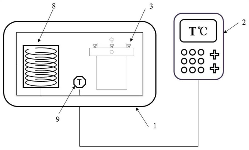
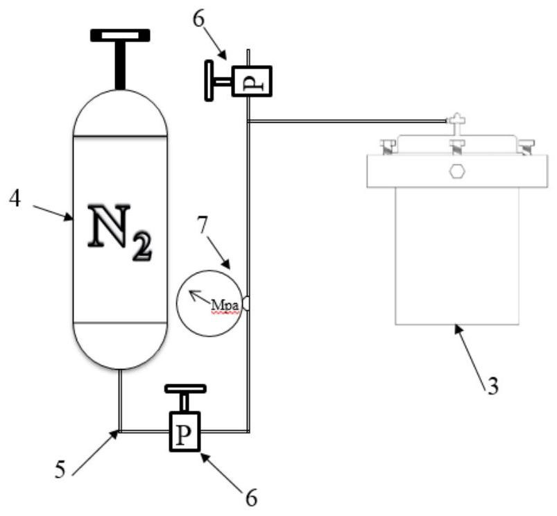
[0056] Such as figure 1 As shown, a cement stone curing device includes: a heating device and a pressurizing device;

[0057] The heating device includes: a constant temperature heating box 1, a temperature controller 2, and a curing kettle 3;

[0058] The inner or outer wall of the constant temperature heating box 1 is provided with a resistance heating wire 8 , and it can also be arranged on the outer wall of the constant temperature heating box 1 to realize heating of the whole box body. Simultaneously, the front of the constant temperature heating box 1 is provided with a box door, and the curing kettles 3 of different sizes can be put into the box for maintenance by opening the box door.

[0059] The outside of the constant temperature heating bo...


PUM


Abstract

The invention discloses a cement curing device and a method for using the same. By heating the inner space of a large constant temperature heating box, the whole curing kettle is heated and kept constant from the outside to the inside, which changes the traditional curing device in the curing kettle. Or the heating method of setting heating resistors on the wall of the kettle body can not only control the temperature in the curing kettle, but also have the advantages of reducing the size of the kettle body, improving the pressure bearing capacity, reducing manufacturing costs, and increasing the space utilization efficiency in the kettle. Multiple single kettles of different sizes can be placed in the constant temperature heating box at the same time, and the number and size of the kettle bodies can be flexibly configured according to needs; by only taking the required small kettles when taking samples, it can also overcome the traditional maintenance device. When the cement stone sample is taken, the temperature and pressure fluctuations of the rest of the cement stone in the curing kettle will cause the performance change of the cement stone, so that the cured cement stone is more in line with the actual cement stone in the well.

Description

technical field [0001] The invention relates to the technical field of oil and gas well cementing, in particular to a method for using a cement maintenance device. Background technique [0002] In cementing engineering, cement stones are usually maintained in a simulated downhole high temperature and high pressure environment, and then various performance tests are performed on the cement stones, and the test results are used as the optimal cement slurry system, optimization of cement slurry formula and control of subsequent process construction parameters. basis etc. Therefore, whether the indoor curing device can truly and quickly simulate the condensation environment of cement slurry in the downhole is very important for efficient and rapid curing of cement stone samples that meet the actual downhole conditions. [0003] The current cement stone curing methods and devices can be divided into two categories, one is atmospheric pressure curing: the pressure in the curing k...

Claims


Application Information

Patent Timeline
Patent Type & Authority Patents(China)
IPC IPC(8): B28B11/24G01N1/28
CPCB28B11/245B28B11/247B28B11/248G01N1/28
Inventor 张兴国涂强周岩杨燕李路宽雷阿山庞佑元杨学松马瑞瑞
Owner SOUTHWEST PETROLEUM UNIV
Why Eureka
Try Eureka