Shock absorption device for ultrasonic welding machine

A technology of ultrasonic welding and welding head, which is applied in the direction of welding equipment, non-electric welding equipment, metal processing equipment, etc. It can solve the problems of workpiece position deviation, etc., and achieve the effect of reducing vibration, convenient replacement and good use effect

Inactive Publication Date: 2021-03-09
JIANGSU OCEAN UNIV
View PDF8 Cites 0 Cited by
  • Summary
  • Abstract
  • Description
  • Claims
  • Application Information

AI Technical Summary

Problems solved by technology

[0004] The purpose of the present invention is to solve the problem that the position of the workpiece will shift due to vibration when the ultrasonic welding machine welds the workpiece in the prior art, and proposes a shock-absorbing device for the ultrasonic welding machine

Method used


Image

  • Shock absorption device for ultrasonic welding machine
  • Shock absorption device for ultrasonic welding machine
  • Shock absorption device for ultrasonic welding machine

Examples


Embodiment Construction

[0025] Next, the technical solutions in the embodiments of the present invention will be apparent from the embodiment of the present invention, and it is clearly described, and it is understood that the described embodiments are merely embodiments of the present invention, not all of the embodiments.

[0026] In the description of the present invention, it is to be understood that the terms "upper", "lower", "front", "post", "left", "right", "top", "bottom", "inside", " The orientation or positional relationship of the instructions such as "is based on the orientation or positional relationship shown in the drawings, which is merely description of the present invention and simplified description, rather than indicating or implying that the device or component must have a specific direction. Specific orientation constructs and operations are therefore not to be construed as limiting the invention.

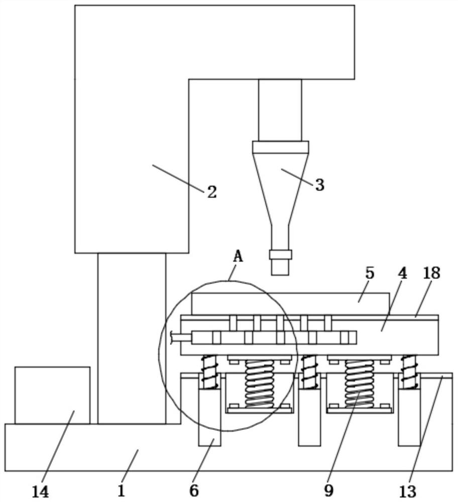
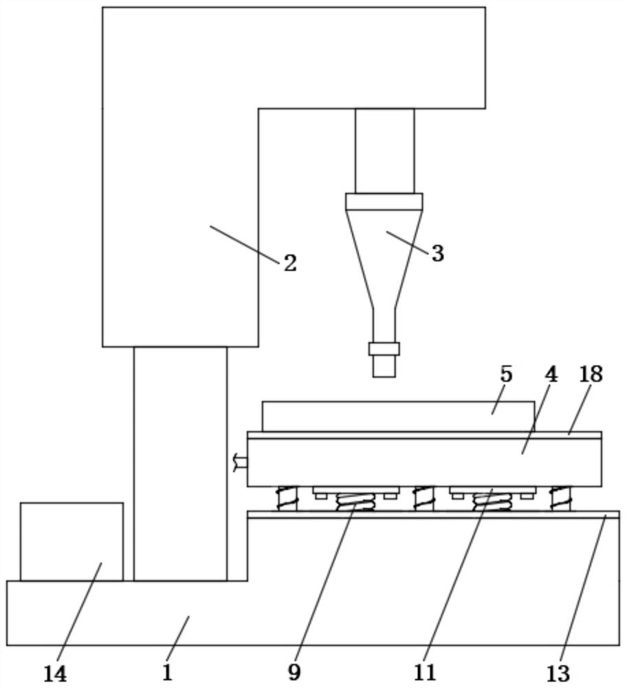
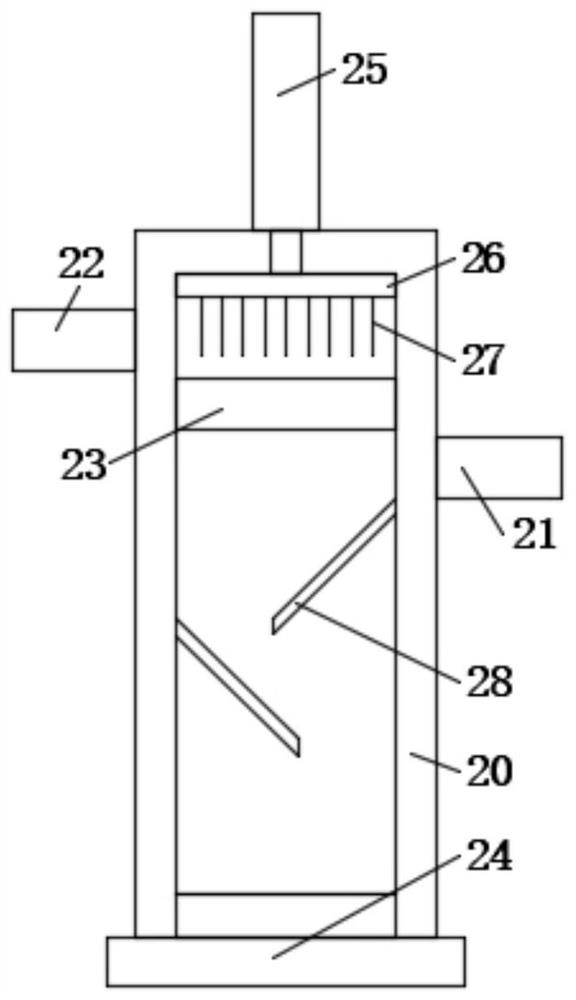
[0027] Refer Figure 1-4 A shock absorbing device for ultrasonic welding machine com...


PUM


Abstract

The invention discloses a shock absorption device for an ultrasonic welding machine. The shock absorption device for the ultrasonic welding machine comprises a base and the ultrasonic welding machinefixedly installed at the top end of the base; a welding head is arranged on the ultrasonic welding machine; a placing platform is movably installed at the top end of the base, and the placing platformis located on the lower side of the welding head; a workpiece is placed on the top wall of the placing platform; a plurality of telescopic rod mother rods are fixedly installed on the base; a telescopic rod son rod is movably inserted into the top end of each telescopic rod mother rod; the top end of each telescopic rod son rod is fixedly installed on the bottom wall of the placing platform; anda first damping spring is arranged on the outer side wall of each telescopic rod son rod in a winding mode. According to the shock absorption device for the ultrasonic welding machine, vibration can be generated when the ultrasonic welding machine works, and the damping effect can be achieved by arranging the first damping springs and second damping springs; in addition, a buffering cushion is arranged, and when the placing platform makes contact with the base, the buffering effect can be achieved; and therefore, the vibration of the workpiece is greatly reduced, and the welding quality is improved.

Description

Technical field [0001] The present invention relates to the field of ultrasonic welding machines, and more particularly to an obsolete device for ultrasonic welding machines. Background technique [0002] Ultrasonic welding machine can be divided into automated welding machine, semi-automatic ultrasonic welding machine, manual welding machine according to the automation level, for modern enterprises, the higher the level of automation, the more conducive to enterprise pipeline production, so the use of automatic welding machine is one of the future Trend, ultrasonic plastic welding principle is a high voltage, high frequency signal, high frequency signal, and convert the signal to high frequency mechanical vibration by a replacement system, and is added to the plastic product workpiece, by the workpiece surface and in molecules When the friction is frozed, the temperature transmitted to the interface rises, when the temperature reaches the melting point of the workpiece itself, t...

Claims


Application Information

Patent Timeline
Patent Type & Authority Applications(China)
IPC IPC(8): B23K20/26B23K20/10
CPCB23K20/26B23K20/10
Inventor 张会霞李师嵇亚东
Owner JIANGSU OCEAN UNIV
Why Eureka
Try Eureka