Auxiliary frame for electric drill machining

An auxiliary frame and electric drill technology, applied in metal processing equipment, workbenches, manufacturing tools, etc., can solve problems such as affecting the installation progress, failing to meet processing requirements, trouble, etc., to ensure processing accuracy, reduce vibration and jitter, ensure The effect of installation progress

Inactive Publication Date: 2021-03-09
义乌融鹄电子科技有限公司
View PDF0 Cites 1 Cited by
  • Summary
  • Abstract
  • Description
  • Claims
  • Application Information

AI Technical Summary

Problems solved by technology

[0003] It generally requires manual hand-held operation, and for some specific processed plates, when the processing accuracy requirements are relatively high, manual hand-held operation cannot meet the processing requirements due to the vibration problem. or other equipment, which is very troublesome, especially in some on-site installations, which cannot realize on-site processing, thus affecting the installation progress

Method used


Image

  • Auxiliary frame for electric drill machining
  • Auxiliary frame for electric drill machining

Examples


Embodiment Construction

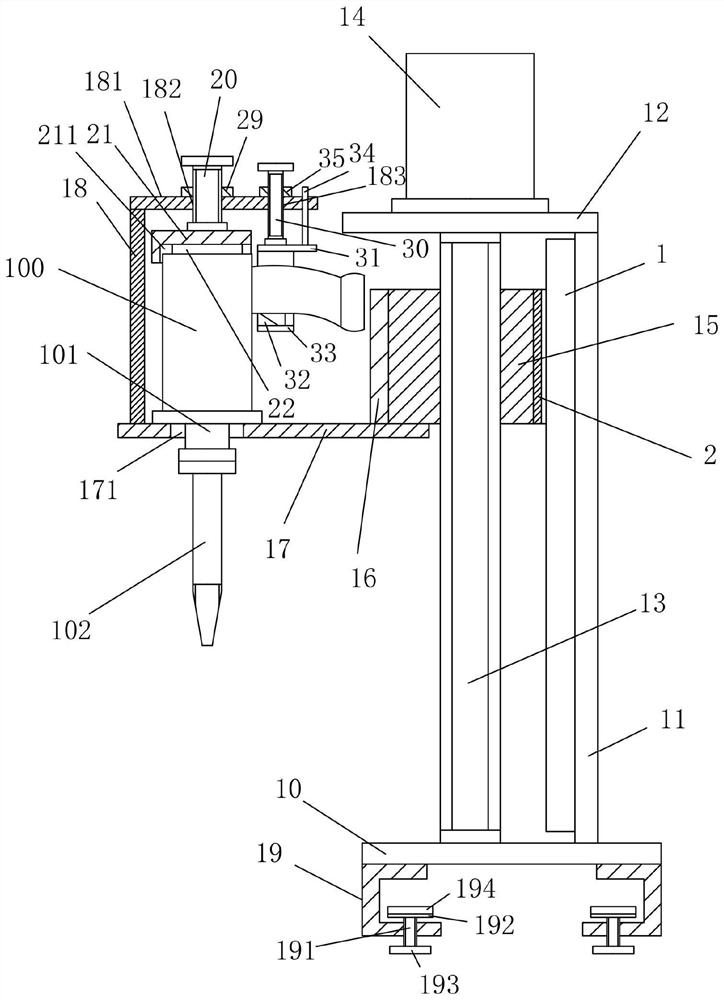
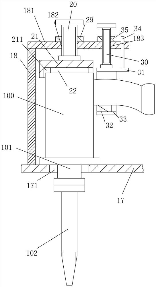
[0019] Examples, see e.g. Figures 1 to 2 As shown, a kind of auxiliary frame for electric drill processing includes a fixed base plate 10, the top surface of the fixed base plate 10 is fixed with a vertical support plate 11, and the upper horizontal plate 12 is fixed on the top surface of the vertical support plate 11, vertically The top of lifting screw rod 13 is hinged on the upper horizontal plate 12 by bearing, and the bottom end of vertical lifting screw rod 13 is hinged on the fixed base plate 10 by bearing, and the top surface of upper horizontal plate 12 is fixed with lifting motor 14, and the lifting motor 14 The output shaft is a spline shaft, and the spline shaft is inserted into the spline hole at the top of the vertical lifting screw 13. The lifting motor 14 drives the vertical lifting screw 13 to rotate, and the vertical lifting screw 13 is screwed with a lifting adjustment block. 15. A connection fixing plate 16 is fixed on the outer side wall of the lifting ad...


PUM


Abstract

The invention discloses an auxiliary frame for electric drill machining. The auxiliary frame comprises a fixed bottom plate, a vertical supporting plate is fixed to the top face of the fixed bottom plate, an upper horizontal plate is fixed to the top face of the vertical supporting plate, the top end of a vertical lifting screw rod is hinged to the upper horizontal plate through a bearing, and thebottom end of the vertical lifting screw rod is hinged to the fixed bottom plate through a bearing; a lifting motor is fixed to the top face of the upper horizontal plate and drives the vertical lifting screw rod to rotate, a lifting adjusting block is connected to the vertical lifting screw rod in a threaded mode, a connecting fixing plate is fixed to the outer side wall of the lifting adjustingblock, a horizontal fixing plate is fixed to the bottom face of the connecting fixing plate, and a mounting through hole is formed in the middle of the outer side of the horizontal fixing plate. An electric drill can be fixed and automatically lifted, the condition that an electric drill bit of the electric drill vertically moves downwards is ensured, vibration and shaking are reduced, the machining precision is guaranteed, the electric drill can directly conduct machining at an existing mounting position, and the mounting progress is guaranteed.

Description

technical field [0001] The invention relates to the technical field of electric tool equipment, in particular to an auxiliary frame for electric drill processing. Background technique [0002] An electric drill is a drilling tool that uses electricity as power. It is a conventional product in electric tools, and it is also the most demanded electric tool product. [0003] It generally requires manual hand-held operation, and for some specific processed plates, when the processing accuracy requirements are relatively high, manual hand-held operation cannot meet the processing requirements due to the vibration problem. It is very troublesome to process on or other equipment, especially in some on-site installation places, which cannot realize on-site processing, thus affecting the installation progress. Contents of the invention [0004] The purpose of the present invention is to overcome the deficiencies of the prior art, and provide an auxiliary frame for electric drill ...

Claims


Application Information

Patent Timeline
Patent Type & Authority Applications(China)
IPC IPC(8): B23B45/14
CPCB25H1/0021
Inventor 闫保建
Owner 义乌融鹄电子科技有限公司
Why Eureka
Try Eureka