
Machine opening adjusting equipment for pipe necking machine

A technology for adjusting equipment and necking, which is applied in metal processing equipment, lighting and heating equipment, dryers, etc., and can solve problems such as slippage of oil guide pipes and adhesion of oil to adjustment plates

Inactive Publication Date: 2021-03-09
广州鑫和信息技术有限公司
View PDF0 Cites 1 Cited by
  • Summary
  • Abstract
  • Description
  • Claims
  • Application Information

AI Technical Summary

Problems solved by technology

[0003] Since a layer of engine oil will remain inside the oil guide pipe after use, and the oil inside the oil guide pipe will flow out to the outer wall of the adjacent oil guide pipe during transportation, if the used oil guide pipe needs to be re-shrunk, It will cause the oil guide pipe with oil on the outer wall of the adjustment plate to be fitted and fixed, and the inner side of the adjustment plate will adhere to the phenomenon of engine oil. If accumulated for a long time, the friction between the adjustment plate and the oil guide pipe will easily decrease, resulting in the squeeze of the oil guide pipe. Slippage occurs when the compression port

Method used


Image

  • Machine opening adjusting equipment for pipe necking machine
  • Machine opening adjusting equipment for pipe necking machine
  • Machine opening adjusting equipment for pipe necking machine

Examples


Embodiment 1

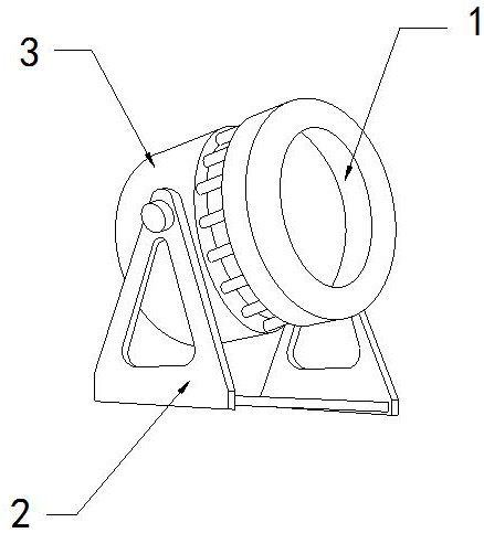
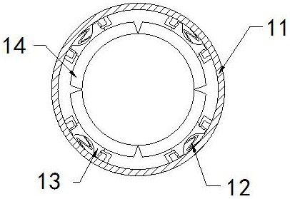
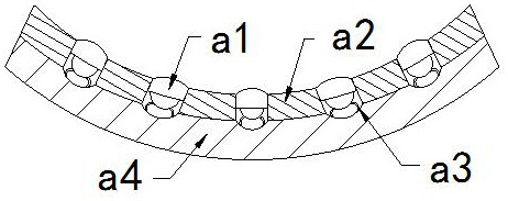
[0026] For example figure 1 -example Figure 5 Shown:

[0027] The invention provides a nozzle adjustment device for a pipe shrinking machine, the structure of which includes an adjustment disc 1, a support frame 2, and a shrinking cavity 3, the shrinking cavity 3 is hingedly connected with the support frame 2, and the adjustment disc 1 is embedded in the Shrink the front end position of cavity 3; Described adjustment plate 1 comprises shell 11, booster bar 12, linkage frame 13, adjustment plate 14, and described booster bar 12 is installed between the inner side of linkage frame 13 and shell 11, described The linkage frame 13 is movably engaged with the housing 11 , and the adjustment plate 14 is fixed at the front end of the linkage frame 13 .

[0028] Wherein, the adjusting plate 14 includes a force-bearing block a1, a contact plate a2, an elastic piece a3, and a bottom plate a4, the force-bearing block a1 and the contact plate a2 are in clearance fit, and the contact pla...

Embodiment 2

[0034] For example Figure 6 -example Figure 8 Shown:

[0035] Wherein, the rotating roller b2 includes a contact plate c1, a resilient piece c2, an engaging plate c3, and a solid plate c4, the contact plate c1 is movably engaged with the solid plate c4, and the resilient piece c2 is installed on the two contact plates Between c1, the connecting plate c3 is embedded in the outer position of the middle solid plate c4, and the contact plates c1 are four, and are evenly distributed in a circular shape on the outer surface of the connecting plate c3, and the thrust generated by the engine oil to the mechanism , the mechanism can be rotated, so that the contact plate c1 can expand outward under the cooperation of the rebound piece c2.

[0036] Wherein, the connecting plate c3 includes a movable ball c31, a frame c32, and an inlet c33. The movable ball c31 is installed inside the frame c32. The inlet c33 and the frame c32 are integrated structures. The inlet c33 There are three,...


PUM


Abstract

The invention discloses machine opening adjusting equipment for a pipe necking machine. The equipment structurally comprises an adjusting disc, a supporting frame and a necking cavity, wherein the necking cavity is connected with the supporting frame through a hinge, the adjusting disc is fixedly embedded in the front end of the necking cavity, a stress block on an adjusting plate is extruded through the outer surface of an oil guide pipe, and the stress block can contract inwards under the cooperation of a contact plate, so that engine oil attached to the inner side of the adjusting plate canenter the stress block through the fall between the stress block and the contact plate, the situation that the oil guide pipe slips in the adjusting disc due to the fact that the engine oil is accumulated on the inner side of the adjusting plate for a long time is effectively avoided, a rotating roller can rotate through thrust generated by more engine oil on the rotating roller, the contact plate can expand outwards under the cooperation of a springback piece through throwing force generated by rotation of the rotating roller, and then the contact plate can cooperate with a plate body and the inner wall of a bottom plate to extrude and rub the engine oil so as to accelerate air drying.

Description

technical field [0001] The invention relates to the field of necking machines, in particular to a mouth adjusting device for a pipe necking machine. Background technique [0002] The nozzle diameter adjustment plate for the pipe necking machine is mainly used to scale the diameter of the pipe necking machine mouth. The diameter of the mouth of the pipe necking machine is changed, so that the pipe necking machine can be applied to pipes of various diameters. Based on the above description, the inventors found that the existing mouth adjustment equipment for a pipe necking machine mainly There are deficiencies such as: [0003] Since a layer of engine oil will remain inside the oil guide pipe after use, and the oil inside the oil guide pipe will flow out to the outer wall of the adjacent oil guide pipe during transportation, if the used oil guide pipe needs to be re-shrunk, It will cause the oil guide pipe with oil on the outer wall of the adjustment plate to be fitted and f...

Claims


Application Information

Patent Timeline
Patent Type & Authority Applications(China)
IPC IPC(8): B21D41/04B21D43/00F26B21/00
CPCB21D41/04B21D43/003F26B21/001
Inventor 蒋芹芹
Owner 广州鑫和信息技术有限公司
Learn More