
Reflector adjusting mechanism, projection ray machine and projector

A technology of adjusting mechanism and projector, applied in optics, instruments, optical components, etc., can solve problems such as difficulty in adjustment, tilting of mirrors, deviation of supports, etc.

Active Publication Date: 2021-03-05
深圳市安华光电技术股份有限公司
View PDF9 Cites 0 Cited by
  • Summary
  • Abstract
  • Description
  • Claims
  • Application Information

AI Technical Summary

Problems solved by technology

In this way, although the adjustment range of each screw is relatively large, it is relatively difficult to adjust in practical applications
Furthermore, if the axis of the screws is perpendicular to the mirror and the screws are threaded to the support, the support has a tendency to rotate about the axis of the screw when one of the screws is adjusted, causing the support to deviate from the axis of the other screws, resulting in mirror tilt
[0004] In summary, it is very difficult to adjust the mirror adjustment device

Method used


Image

  • Reflector adjusting mechanism, projection ray machine and projector
  • Reflector adjusting mechanism, projection ray machine and projector
  • Reflector adjusting mechanism, projection ray machine and projector

Examples


Embodiment Construction

[0039] In order to better illustrate the technical solutions and beneficial effects of the mirror adjustment device of the present invention, before introducing the detailed structure of the mirror adjustment device of the present invention, a projection optical machine in a preferred embodiment of the present invention is firstly introduced.

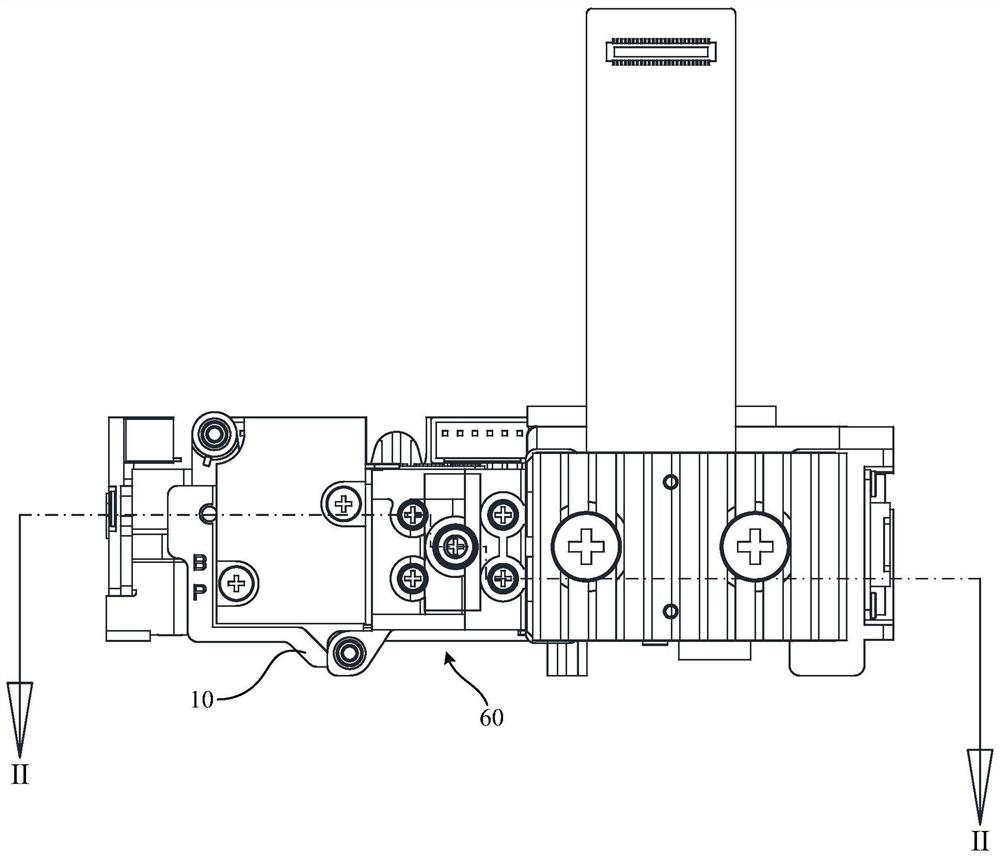
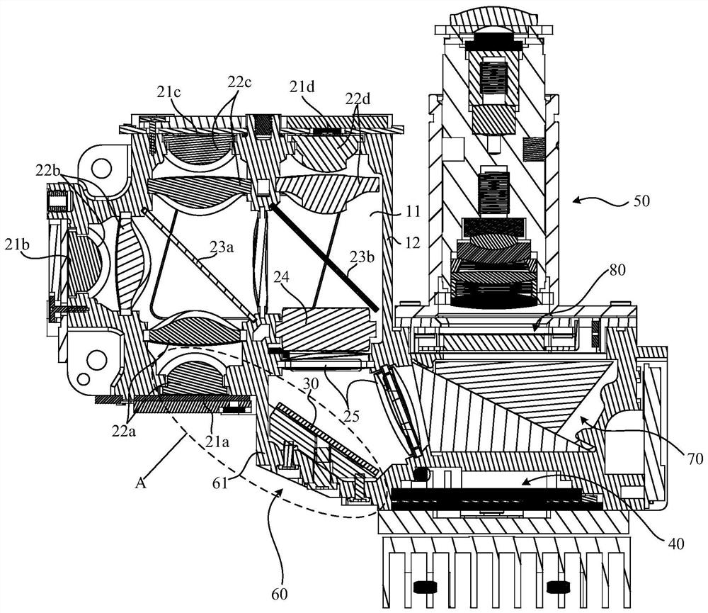
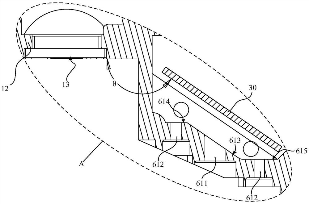
[0040] Please refer to Figure 1 to Figure 4 , in one embodiment, the optical projection machine of the present invention includes a housing 10, an optical lighting system (not marked), a reflector 30, an image modulation element 40, a projection lens 50, and a reflector adjustment mechanism 60; the reflector 30 It is fixed on the support member 62 of the mirror adjustment mechanism 60 .

[0041] in,

[0042] The optical lighting system is used to generate parallel three-color light, and its specific composition has many variations according to the prior art. In this embodiment, specifically, the optical illumination system includes a...


PUM


Abstract

The invention discloses a reflector adjusting mechanism, a projection ray machine and a projector. The reflector adjusting mechanism comprises a fixed seat, a support member, a connecting member and aplurality of adjusting members, wherein the fixed seat is provided with a through hole and a plurality of adjusting holes, and the through hole and the adjusting holes extend in parallel; the supportmember is opposite to the fixed seat and provided with a threaded hole corresponding to the through hole. The back of the support is used for fixing the bearing reflector; the rod part of the connecting member penetrates through the through hole and is connected with the threaded hole, and the head part abuts against the front surface of the fixed seat; the adjusting members are arranged in the adjusting holes in a one-to-one correspondence mode and act on the support member in the axis direction of the adjusting holes so that the supporting member can swing relative to the fixed seat. The back face of the fixed seat comprises a first limiting face, all tangential directions corresponding to the screwing-in circumferential direction of the connecting member intersect with the first limiting face, and the support member is matched with the first limiting face in a limiting mode. The reflector adjusting mechanism is easy to adjust the reflector, and the reflector is not easy to rotate around the axis of the connecting piece.

Description

technical field [0001] The invention relates to the technical field of optical projection equipment, in particular to a mirror adjustment mechanism, a projection light machine and a projector. Background technique [0002] The core component of the micro projector is the projection light machine. The projection light machine is designed with the portability of the micro projector in mind, and it is often necessary to set a reflector inside the optical lighting system to change the direction of the light path. In practical applications, due to the high precision of the projector system, there are many links that affect the projection quality. Among them, the installation accuracy of the reflector is one of the key links, due to the correct realization of the function of the reflector itself, and the error of other links For compensation, the projector also includes a reflector adjustment device for adjusting the reflector. [0003] In the existing reflector adjustment devic...

Claims


Application Information

Patent Timeline
IPC IPC(8): G03B21/28G02B7/182
CPCG03B21/28G02B7/182
Inventor 邓朝山吴积涛孙峰朱青
Owner 深圳市安华光电技术股份有限公司
Learn More