Rapid automatic leveling load-bearing element structure and mounting method

A component and automatic technology, applied in the direction of building structure, floor, covering/lining, etc., can solve the problems that affect the accuracy of splicing, complicated installation, complicated procedures, etc., and achieve the effect of increasing the overall height

Pending Publication Date: 2021-03-05
ZHEJIANG YASHA DECORATION
View PDF2 Cites 0 Cited by
  • Summary
  • Abstract
  • Description
  • Claims
  • Application Information

AI Technical Summary

Problems solved by technology

However, the existing light steel keel is limited by its own size and specifications, the installation structure is complicated, and the leveling base takes up a lot of space, so it is not suitable for small spaces.
The CN201710246897.X patent authorized by the Chinese Patent Office on June 16, 2020 is called a wall leveling system and leveling method. The device is used on the wall, and the device is provided with an adjustment block on the side of the vertical keel facing the wall. , the adjustment block is connected to the adjustment stud through the threaded hole, and the adjustment stud is adjusted against the wall to form a side support for the vertical keel, so as to realize the rapid leveling of the wall. , there will be a large leveling error; the adjustment block and the adjustment stud need to cooperate with each other, and the adjustment block and the adjustment stud are mutually independent structures, and the installation is more complicated; the adjustment stud in the threaded hole of the adjustment block needs to be rotated, Only when the adjusting stud is against the wall can the adjustment be completed, the leveling method cannot be in place at one time, and manual continuous adjustment is required
[0003] In addition, the traditional floor leveling structure is relatively complicated. Since the leveling parts are arranged under the load-bearing plates, leveling cannot be performed after the load-bearing plates are installed, resulting in poor leveling accuracy; some existing methods set leveling parts at the joints of the load-bearing plates. The load-bearing plates can be installed first and then leveled, but there will be gaps between the load-bearing plates in this method, which will affect the accuracy of splicing. In addition, during leveling, the leveling parts are difficult to move under the gravity of the load-bearing plates, which increases the difficulty of leveling
For example, the CN201920270352.7 patent authorized by the Chinese Patent Office on February 07, 2020 is called a prefabricated floor leveling structure. The leveling method still adopts a full thread structure, and the leveling speed is not convenient enough. It needs continuous adjustment and manual feeling to complete it. Leveling, and there is a certain risk of misleveling
[0004] The support members and leveling members of the general ground / wall leveling load-bearing components are mostly designed with full threads. In practical applications, manual continuous leveling is required to continuously adjust to the leveling height, and fast automatic leveling cannot be achieved. The process is complicated and labor-intensive. long

Method used


Image

  • Rapid automatic leveling load-bearing element structure and mounting method
  • Rapid automatic leveling load-bearing element structure and mounting method
  • Rapid automatic leveling load-bearing element structure and mounting method

Examples


Embodiment Construction

[0040] In order to make the purpose, technical solutions and advantages of the embodiments of the present invention clearer, the technical solutions in the embodiments of the present invention will be clearly and completely described below in conjunction with the drawings in the embodiments of the present invention. Obviously, the described embodiments It is a part of embodiments of the present invention, but not all embodiments. Based on the embodiments of the present invention, all other embodiments obtained by persons of ordinary skill in the art without making creative efforts belong to the protection scope of the present invention. It should be noted that, in the case of no conflict, the embodiments in the present application and the features in the embodiments can be combined arbitrarily with each other.

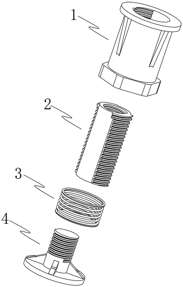
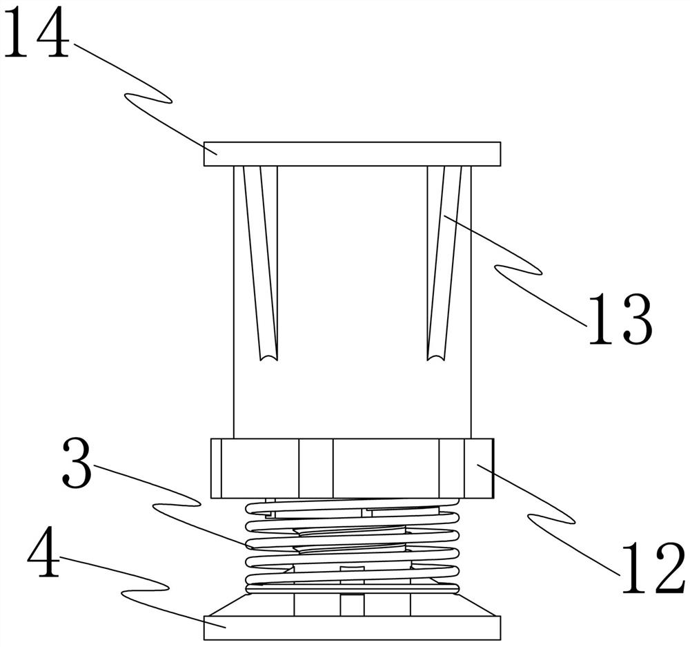
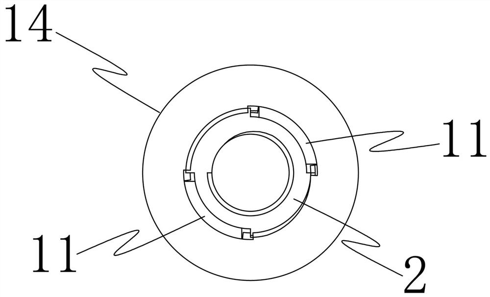
[0041] In order to solve the above problems, the present invention proposes a fast self-leveling load-bearing member structure, please refer to figure 1 , figure 2 ...


PUM


Abstract

The invention discloses a rapid automatic leveling load-bearing element structure and a mounting method. The element comprises a supporting sleeve, a leveling shaft, a spring, and a base; an inner half thread is arranged in the supporting sleeve; an outer half thread is arranged outside the leveling shaft; the leveling shaft is connected with the base; the spring is arranged on the leveling shaftin a sleeving mode and abuts against the base; the inner half thread and the outer half thread can be matched to form a threaded connection structure, so that the supporting sleeve can be screwed on the leveling shaft and compress the spring; the width of a non-arranged thread in the supporting sleeve is the same as the width of the outer half thread outside the leveling shaft; and when the innerhalf thread does not make contact with the outer half thread, the supporting sleeve can be bounced by the spring in the axis direction of the leveling shaft. According to the rapid automatic levelingload-bearing element, a structure composed of the supporting sleeve, the leveling shaft and the base serves as a load-bearing element, and the height can be automatically and rapidly adjusted and leveled through the utilization of the spring, so that leveling can be completed at a time only by rotating the supporting sleeve twice.

Description

technical field [0001] The invention relates to the technical field of floor / wall board laying, in particular to a fast and automatic leveling load-bearing member structure and an installation method. Background technique [0002] In the traditional decoration industry, base treatment is an important link in construction; for wall base treatment, there are mainly two forms of wet leveling and dry leveling for different facing materials. The wet leveling process is complicated, time-consuming and labor-intensive. Serious pollution to the construction site; dry leveling is mainly in the form of keel veneer walls, and its materials include wooden keel and light steel keel. The wooden keel itself does not meet the requirements of fire protection codes, and it is necessary to carry out secondary fire protection and anticorrosion on the material on site. The light steel keel not only meets the requirements of fire protection, anti-corrosion, and insect-proof, but also has the adva...

Claims


Application Information

Patent Timeline
IPC IPC(8): E04F13/23E04F15/02
CPCE04F13/0801E04F15/02
Inventor 丁欣欣丁泽成王文广周东珊王晓杰武鹏余文钊许伟张西亮
Owner ZHEJIANG YASHA DECORATION
Why Eureka
Try Eureka