
A Leg-Foot Mechanism of a High-performance Bionic Footed Robot

A robot and high-performance technology, applied in the field of hexapod robots, can solve problems such as inability to adjust according to actual use requirements, complex foot installation structure, and inconvenient users, and achieve the effect of simple structure, convenient replacement, and strong practicability

Active Publication Date: 2021-11-30
NANJING YUZHI INTELLIGENT TECH CO LTD
View PDF6 Cites 0 Cited by
  • Summary
  • Abstract
  • Description
  • Claims
  • Application Information

AI Technical Summary

Problems solved by technology

[0004] During the actual use of the hexapod robot, the length of its legs is fixed and cannot be adjusted according to the actual use requirements. At the same time, due to the long-term use of the hexapod robot, its feet are in direct contact with the ground, so the wear is very large. Therefore, it is necessary to replace the feet in time, but the existing foot installation structure is complex and not easy to replace. to solve the above-mentioned problems

Method used


Image

  • A Leg-Foot Mechanism of a High-performance Bionic Footed Robot
  • A Leg-Foot Mechanism of a High-performance Bionic Footed Robot
  • A Leg-Foot Mechanism of a High-performance Bionic Footed Robot

Examples


Embodiment 1

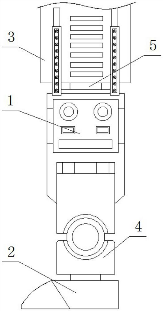
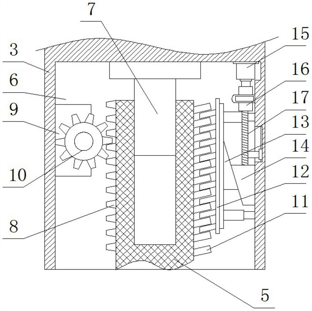
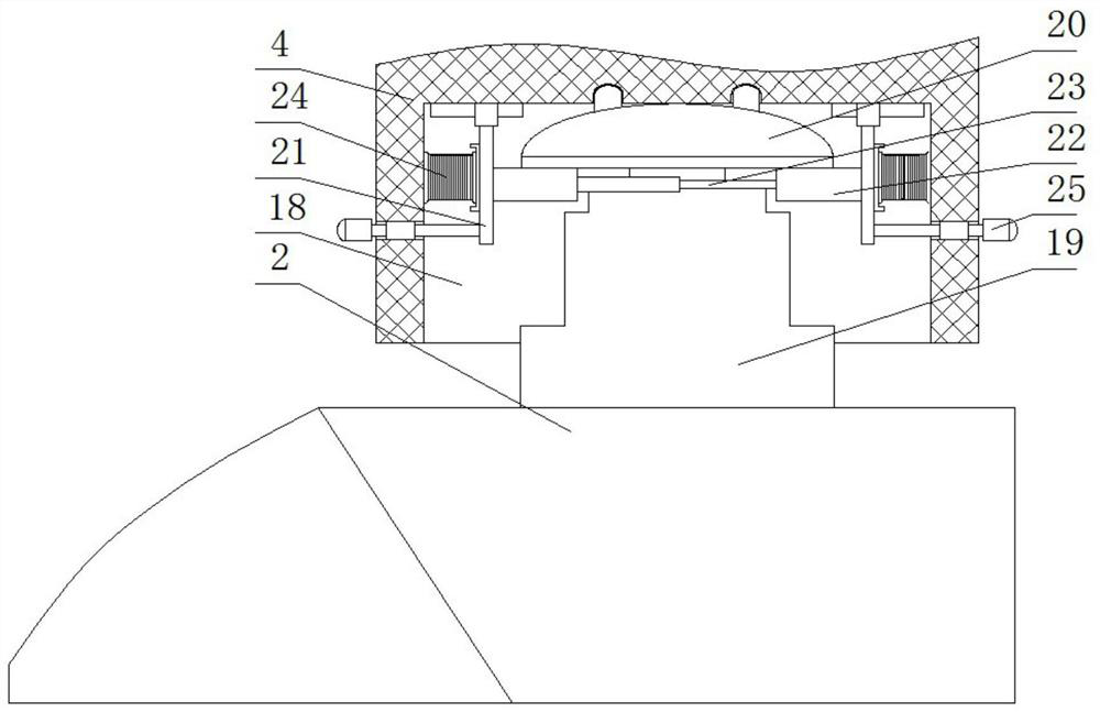
[0032] see Figure 1-5 , the present embodiment provides a leg-foot mechanism of a high-performance bionic footed robot, a leg-foot mechanism of a high-performance bionic footed robot, comprising a mechanical leg 1 and a mechanical foot 2, the bottom of the mechanical leg 1 is fixed Mounting base 4 is installed, mechanical foot 2 is detachably and fixedly installed on the bottom of mounting base 4, the top of mechanical leg 1 is slidably connected with lifting block 3, and the bottom of lifting block 3 is provided with lifting assembly.

[0033] Among them, the lifting assembly includes an adjustment groove 6 provided at the bottom of the lifting block 3, a slide bar 7 is fixedly installed on the top inner wall of the adjustment groove 6, and the bottom of the slide bar 7 is slidably connected with the lifting rod 5, and the bottom of the lifting rod 5 and the mechanical leg The top of the part 1 is fixedly connected, one side of the lifting rod 5 is fixedly installed with a d...

Embodiment 2

[0038] see Figure 1-5 , made further improvement on the basis of embodiment 1:

[0039] In this embodiment, the sides of the two push plates 21 away from each other are respectively fixed with pull rods 25, and the two pull rods 25 respectively pass through the inner walls on both sides of the two mounting grooves 18 and extend to both sides of the mounting seat 4, 25 is convenient to pull push plate 21 to move.

[0040] In this embodiment, a slider is fixedly installed on the top of the push plate 21, and two symmetrically arranged slide rails are fixedly installed on the top inner wall of the installation groove 18, and the two sliders are respectively slidably connected with the two slide rails. The blocks and slide rails can make the push plate 21 move in a straight line all the time without offset.

[0041] In this embodiment, the telescopic rod 23 includes a first sleeve and a second sleeve, and the first sleeve is sleeved on the outside of the second sleeve and is sl...


PUM


Abstract

The invention discloses a leg-foot mechanism of a high-performance bionic foot-type robot, a leg-foot mechanism of a high-performance bionic foot-type robot, comprising a mechanical leg and a mechanical foot, and the bottom of the mechanical leg is fixedly installed with a mounting device. The mechanical foot is detachably fixed on the bottom of the mounting seat, the top of the mechanical leg is slidably connected with a lifting block, and the bottom of the lifting block is provided with a lifting component, and the lifting component includes a lifting block opened at the bottom of the lifting block A sliding rod is fixedly installed on the top inner wall of the regulating groove, and a lifting rod is slidably connected to the bottom of the sliding rod. The present invention has a simple structure, the leg-foot mechanism body of the hexapod robot can adjust the length of the mechanical legs, and at the same time, the quick disassembly and assembly structure set on the mechanical feet greatly facilitates the user to replace the mechanical feet, and the operation is simple. It meets the needs of people and has strong practicability.

Description

technical field [0001] The invention relates to the related technical field of hexapod robots, in particular to a leg-foot mechanism of a high-performance bionic foot robot. Background technique [0002] In nature and human society, there are some places that humans cannot reach and special occasions that may endanger human life. Such as the surface of the planet, disaster mines, disaster prevention and rescue, and anti-terrorism struggle, etc., to continuously explore and study these dangerous environments, and to seek a feasible way to solve problems has become the need for the development of science and technology and the progress of human society. Irregularity and rough terrain are common features of these environments. Thereby the application of wheeled robot and tracked robot is limited. Previous studies have shown that wheeled mobility has considerable advantages when driving on relatively flat terrain, with fast and stable movement speed, and relatively simple stru...

Claims


Application Information

Patent Timeline
Patent Type & Authority Patents(China)
IPC IPC(8): B62D57/032
CPCB62D57/032
Inventor 刘勇强王荣东蒋博慧
Owner NANJING YUZHI INTELLIGENT TECH CO LTD
Learn More