
Conductive rotary table

A turntable and conductive layer technology, applied in the field of additive and subtractive material manufacturing, can solve the problems of wire winding on the workbench, overall electrification of components, and high cost, and achieve the effects of avoiding wire winding problems, good insulation effect, and improved safety.

Pending Publication Date: 2021-03-05
KEDE NUMERICAL CONTROL CO LTD
View PDF0 Cites 0 Cited by
  • Summary
  • Abstract
  • Description
  • Claims
  • Application Information

AI Technical Summary

Problems solved by technology

[0002] The current actual use of the turntable directly connects the circuit to the workpiece, resulting in the problem of wire winding during the rotation of the workbench; if the upper workbench is charged and not insulated, it will cause the entire part to be charged, which poses a safety hazard; usually, the upper and lower The worktop needs to be connected with screws to maintain strength and rigidity, but metal screws themselves are not optional for electrical conductivity. If you replace them with commonly used plastic, nylon and other screws, you can connect the worktop but the rigidity cannot be guaranteed; currently the more popular ceramic materials in the market, its rigidity can be guaranteed , but the characteristics of ceramics are too rigid and fragile, and the current cost is relatively high, so it is not suitable for connecting screws
[0003] At the same time, in processes such as welding and EDM, high-power conductive turntables generally require 8 cables to operate; but for some small-scale processing requirements, such high-power conductive turntables will cause high production costs and high energy consumption.
At present, there is a technical gap for low-power turntables that can not only insulate, power the table, but also brake

Method used


Image

  • Conductive rotary table
  • Conductive rotary table
  • Conductive rotary table

Examples


Embodiment 1

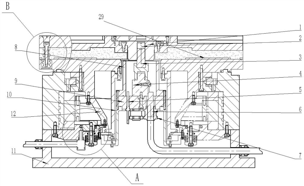
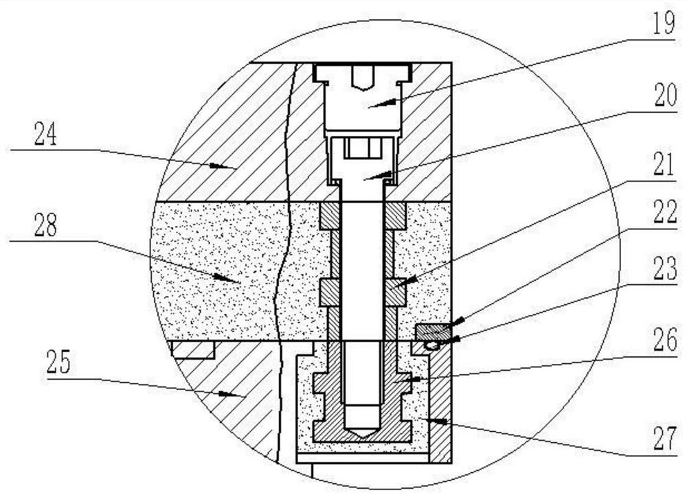
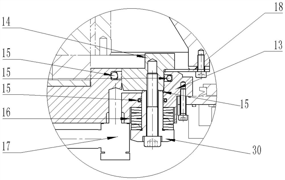
[0032] A conductive turntable, including a workbench, a mandrel 1, an electric slip ring 3, and a collector column 4; the electric slip ring 3 includes a rotating end and a fixed end, and the mandrel 1 is connected to the rotating end of the electric slip ring Connection; the fixed end of the electric slip ring 3 is connected to the collector column 4, the lower end of the collector column 4 is provided with a connecting plate 9, the lower end of the connecting plate 9 is provided with a bracket 10, and the bracket 10 is connected with the fixed plate 13 in the clamping mechanism , the connection plate 9 is provided with a temperature sensor 5 and an external cable 6; the upper plane of the connection plate 9 is provided with a protective plate 8, and the workbench includes a conductive layer 24, an insulating layer 28, and a lower workbench 25; the conductive layer 24, The insulating layer 28 and the lower workbench 25 are sequentially connected from top to bottom through the ...


PUM


Abstract

The invention belongs to the technical field of additive and subtractive manufacturing of welding, electric sparks, electric arcs and the like, and discloses a conductive rotary table. The conductiverotary table comprises a workbench, a mandrel, an electric slip ring, a current collection column and a clamping mechanism. The electric slip ring comprises a rotating end and a fixed end, and the mandrel is connected with the rotating end of the electric slip ring. The fixed end of the electric slip ring is connected with the current collection column, the lower end of the current collection column is provided with a connection disc, the lower end of the connection disc is provided with a support, the support is connected with a fixed disc in the clamping mechanism, the two vertical faces ofthe connection disc are provided with protection plates, and the workbench comprises a conductive layer, an insulation layer and a lower workbench body. The device has the characteristics of insulation, table top power supply, braking, low power and energy conservation.

Description

technical field [0001] The invention belongs to the technical fields of welding, electric spark, electric arc and other additive and subtractive material manufacturing. The invention specifically relates to an energy-saving and high-precision rotary workbench with power supply and insulation performance on the tabletop. Background technique [0002] The current actual use of the turntable directly connects the circuit to the workpiece, resulting in the problem of wire winding during the rotation of the workbench; if the upper workbench is charged and not insulated, the whole part will be electrified, posing a safety hazard; usually, the upper and lower The worktop needs to be connected with screws to maintain strength and rigidity, but metal screws themselves are not optional for electrical conductivity. If you replace them with commonly used plastic, nylon and other screws, you can connect the worktop but the rigidity cannot be guaranteed; currently the more popular ceramic...

Claims


Application Information

Patent Timeline
Patent Type & Authority Applications(China)
IPC IPC(8): B23K37/04B23K37/00B23H11/00B23H1/00
CPCB23H1/00B23H11/003B23K37/003B23K37/0461
Inventor 林阳王连炀鞠兹丹王峰陈霖宫兴林韦志鸿李亚鹏
Owner KEDE NUMERICAL CONTROL CO LTD
Learn More