
Cable erecting device and erecting method thereof

A cable and installation slot technology, applied in overhead lines/cable equipment, electrical components, etc., can solve the problems of cable sheath wear, prolonged construction time, wasted time, etc., to reduce frictional resistance, optimize labor costs, and ensure safety. Effect

Pending Publication Date: 2021-03-02
MCC TIANGONG GROUP
View PDF0 Cites 0 Cited by
  • Summary
  • Abstract
  • Description
  • Claims
  • Application Information

AI Technical Summary

Problems solved by technology

[0004] (1) Multiple manpower is required to complete the cable erection, which wastes manpower;
[0005] (2) Only one cable can be erected at a time, prolonging the construction time and wasting time;
[0006] (3) When the cable is dragged, the steel hook will cause wear to the cable sheath, and the cable will drag the floor, causing a safety hazard

Method used


Image

  • Cable erecting device and erecting method thereof
  • Cable erecting device and erecting method thereof
  • Cable erecting device and erecting method thereof

Examples


Embodiment Construction

[0031] In order to make the object, technical solution and advantages of the present invention clearer, the present invention will be further described in detail below in combination with specific embodiments and with reference to the accompanying drawings. It should be understood that these descriptions are exemplary only, and are not intended to limit the scope of the present invention. Also, in the following description, descriptions of well-known structures and techniques are omitted to avoid unnecessarily obscuring the concept of the present invention.

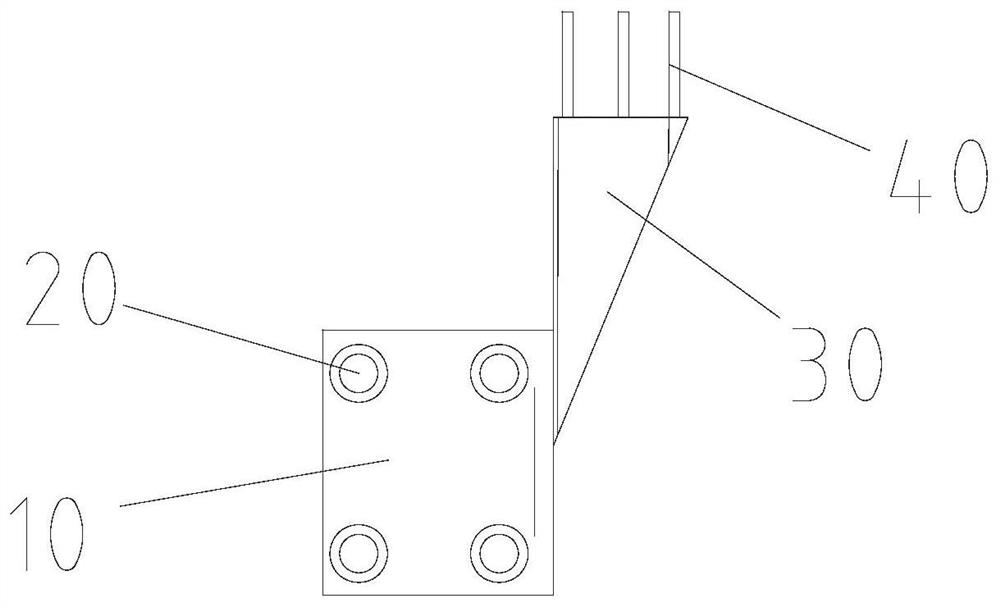
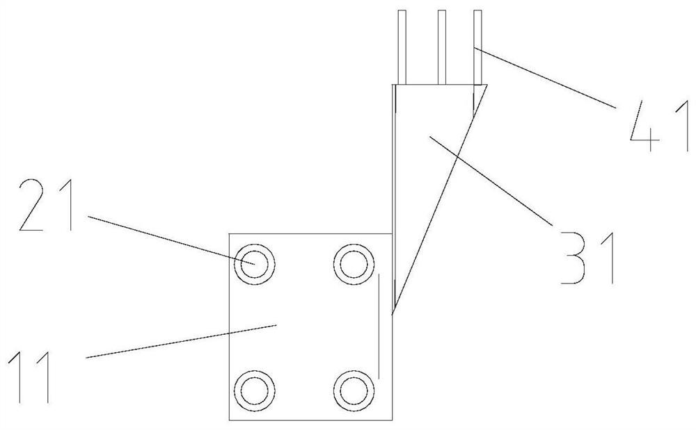
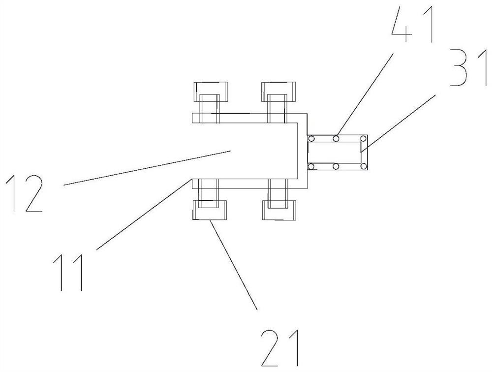
[0032] Such as Figure 1-3 , In the embodiment of the present application, the present application provides a cable erection device, including: an installation assembly 10, an adjustment assembly 20, a support assembly 30 and a rotation assembly 40, each part will be described in detail below.

[0033] Such as Figure 1-3 , in the embodiment of this application, a cable erection device provided by this application inclu...


PUM


Abstract

A cable erecting device and an erecting method thereof belong to the technical field of buildings, and the device comprises: a mounting assembly used for being mounted on a wall body, wherein the mounting assembly is arranged on the wall body; an adjusting assembly which is used for adjusting the position of the mounting assembly on the wall body, wherein the adjusting assembly is arranged on themounting assembly and abuts against the wall body; a supporting assembly which is used for supporting the cable, wherein the supporting assembly is arranged on the mounting assembly; and a rotating assembly which is used for winding the cable on the supporting assembly, wherein the rotating assembly is arranged on the supporting assembly in a rotatable mode. The cable erecting device and the erecting method thereof provided by the invention have the following beneficial effects: (1) a plurality of brackets can be mounted, and a plurality of cables can be erected at the same time; and (2) the supporting rod can rotate in the sleeve, so that the frictional resistance between the supporting rod and the cable is greatly reduced, and the abrasion of the surface of the cable is reduced.

Description

technical field [0001] The invention belongs to the technical field of construction, and in particular relates to a cable erection device and an erection method thereof. Background technique [0002] In the prior art, the cable erection method is to install steel bar hooks on the wall, and then install the cables in the steel bar hooks. However, this method can only set up one cable at a time, which has limitations, and the cable cannot be fixed, which is easy to cause the cable to fall and drag the floor, which has potential safety hazards in construction. [0003] Specifically, the prior art has the following disadvantages: [0004] (1) Multiple manpower is required to complete the cable erection, which wastes manpower; [0005] (2) Only one cable can be erected at a time, prolonging the construction time and wasting time; [0006] (3) When the cable is dragged, the steel bar hook causes abrasion to the cable sheath, and the cable drags the floor, causing potential safe...

Claims


Application Information

Patent Timeline
Patent Type & Authority Applications(China)
IPC IPC(8): H02G1/04H02G3/30B65H75/02
CPCB65H75/02H02G1/04H02G3/30
Inventor 袁涛王康旭陶月波段晔韩泽林
Owner MCC TIANGONG GROUP
Learn More