Eureka AIR delivers breakthrough ideas for toughest innovation challenges, trusted by R&D personnel around the world.

Property monitoring system

A monitoring system and property technology, applied in CCTV systems, components of TV systems, TVs, etc., can solve problems such as inability to take into account the two directions at the corner of buildings, inability to ensure comprehensive security, and inability to move camera surveillance.

Active Publication Date: 2021-03-02
鹏祥智慧保安有限公司
View PDF7 Cites 0 Cited by
  • Summary
  • Abstract
  • Description
  • Claims
  • Application Information

AI Technical Summary

Problems solved by technology

[0002] Surveillance system is one of the most widely used systems in security systems. The more suitable surveillance system on the market is handheld video communication equipment. Video surveillance is now the mainstream. Surveillance is used in various fields. A lot of surveillance systems are also installed for reasons such as property safety and ease of management. However, the surveillance systems installed in the existing community cannot take into account the two directions at the corner of the building. It is easy to form a blind spot between multiple buildings in the community that cannot be photographed. Comprehensive security cannot be guaranteed, and the position of the existing camera monitoring cannot be moved after installation, let alone adjust the angle of view according to the location of the facilities in the community to ensure comprehensive monitoring

Method used


Image

  • Property monitoring system
  • Property monitoring system
  • Property monitoring system

Examples


specific Embodiment approach 1

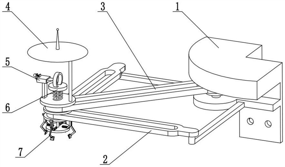
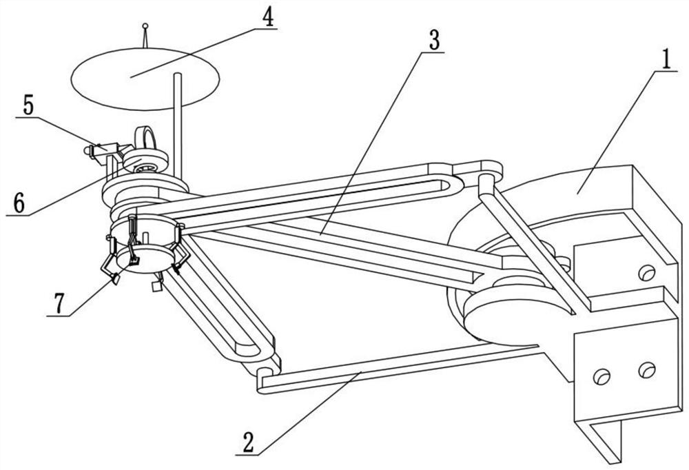
[0028] This embodiment will be described below in conjunction with the drawings. The present invention relates to the technical field of monitoring systems, more specifically a property monitoring system, including a wall connection component 1, a mobile platform component 2, a position moving component 3, a moving base component 4, The telescopic locking assembly 5 and the telescopic sliding assembly 6, the telescopic sliding assembly 6 is connected to the mobile base assembly 4, the telescopic locking assembly 5 is connected to the mobile base assembly 4, and the mobile base assembly 4 is connected to the mobile platform On the component 2, the position moving component 3 is connected to the mobile base component 4 and the wall connection component 1, and the mobile platform component 2 is connected to the wall connection component 1.

[0029] Firstly, the wall connection assembly 1 is fixed on the corner of the building by expansion bolts, and then the camera mounting base i...

specific Embodiment approach 2

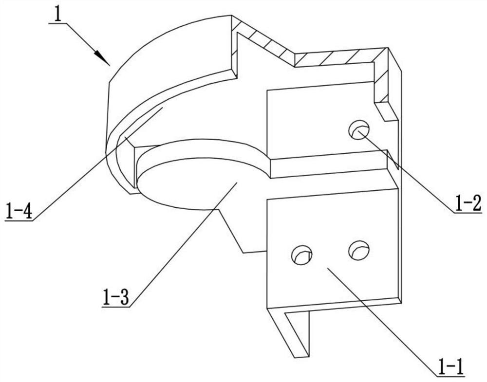
[0031] This embodiment will be described below in conjunction with the drawings. This embodiment will further illustrate Embodiment 1. The wall connection assembly 1 includes a connecting right-angle plate 1-1, a bolt connection hole 1-2, a middle mounting plate 1-3 and a protective cover The roof 1-4, the protective cover roof 1-4 is fixedly connected to the connecting right-angle plate 1-1, and the connecting right-angle plate 1-1 is provided with a plurality of bolt connection holes 1-2, and the middle mounting plate 1-3 is fixedly connected to the connecting plate 1-1. Right angle plate 1-1 middle part.

[0032] Attach the connecting right-angled plate 1-1 to the corner of the building, and then use expansion bolts to fix the connecting right-angled plate 1-1 on the corner of the building through a plurality of bolt connection holes 1-2. The protective covering roof 1-4 can The middle mounting plate 1-3 is protected from rain, and at the same time, it can protect the expan...

specific Embodiment approach 3

[0034] The present embodiment will be described below in conjunction with the drawings. This embodiment will further illustrate the second embodiment. The mobile platform assembly 2 includes a connecting beam 2-1, a sliding plate 2-2 and a right-angle sliding hole 2-3, and the sliding plate 2- 2. It is fixedly connected to the two connecting beams 2-1. The sliding plate 2-2 is provided with a right-angle sliding hole 2-3. The two connecting beams 2-1 are fixedly connected to the middle mounting plate 1-3.


PUM


Abstract

The invention relates to the technical field of monitoring systems, and particularly relates to a property monitoring system. The property monitoring system gives consideration to two directions of acorner of a building, and comprises a wall connecting assembly, a moving platform assembly, a position moving assembly, a moving base assembly, a telescopic locking assembly and a telescopic sliding assembly. A driving gear can be driven to rotate through a rotating motor, the driving gear drives a driven gear to rotate, the driven gear drives a rotating vertical shaft to rotate, and therefore a swing cross beam rotates along with the rotating vertical shaft. When the swing cross beam swings, a pushing shaft can slide in a swing sliding groove, meanwhile, the swing cross beam drives the pushing shaft to drive a rectangular limiting block to slide in a right-angle sliding hole, a middle circular plate and a lower circular plate slide on the upper face and the lower face of a sliding flat plate, and therefore moving adjustment of a camera is completed. When facilities in a community move, the camera can move to adjust the monitoring angle of the camera, and the situation that due to facility moving, the places cannot be shot by the monitoring view angle is avoided.

Description

technical field [0001] The invention relates to the technical field of monitoring systems, in particular to a property monitoring system. Background technique [0002] Surveillance system is one of the most widely used systems in security systems. The more suitable surveillance system on the market is handheld video communication equipment. Video surveillance is now the mainstream. Surveillance is used in various fields. A lot of surveillance systems are also installed for reasons such as property safety and ease of management. However, none of the surveillance systems installed in the existing community can take into account the two directions at the corner of the building. It is easy to form a blind spot between multiple buildings in the community that cannot be photographed. Comprehensive security cannot be guaranteed, and the position of the existing camera monitoring cannot be moved after installation, let alone adjusting the angle of view according to the location chan...

Claims


Application Information

Patent Timeline
IPC IPC(8): F16M13/02F16M11/04F16M7/00H04N5/232H04N7/18
CPCF16M13/02F16M11/046F16M11/041F16M11/18F16M7/00H04N7/181H04N23/695
Inventor 魏永涛佟万国
Owner 鹏祥智慧保安有限公司
Why Eureka
Eureka Blog
Learn More