
Zipper coded lock

A combination lock and zipper technology, which is applied in the field of zipper combination locks, can solve problems such as laborious unlocking process, large wear degree, complex structure, etc., achieve compact and smooth transmission process, improve service life, and optimize transmission relationship.

Pending Publication Date: 2021-03-02
YIFENG MFG
View PDF0 Cites 1 Cited by
  • Summary
  • Abstract
  • Description
  • Claims
  • Application Information

AI Technical Summary

Problems solved by technology

[0003] This kind of locking block moves horizontally to unlock the structure, the structure is complex, and the degree of wear is large. After a long time of use, it will cause problems such as difficulty in unlocking or loose locking. In addition, when unlocking, the lock block needs to move a long distance in translation It can release the locking of the lock hook. Therefore, a large force needs to be applied to the lock block to make the lock block reach the unlocked position. The unlocking process is laborious and the unlocking is not smooth enough.

Method used


Image

  • Zipper coded lock
  • Zipper coded lock
  • Zipper coded lock

Examples


Embodiment 1

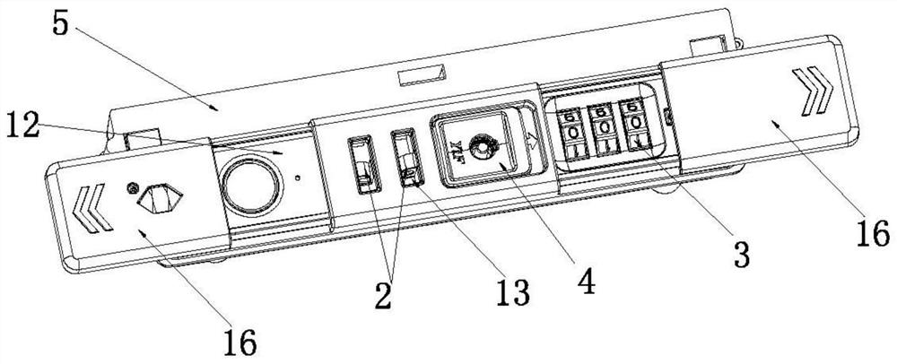
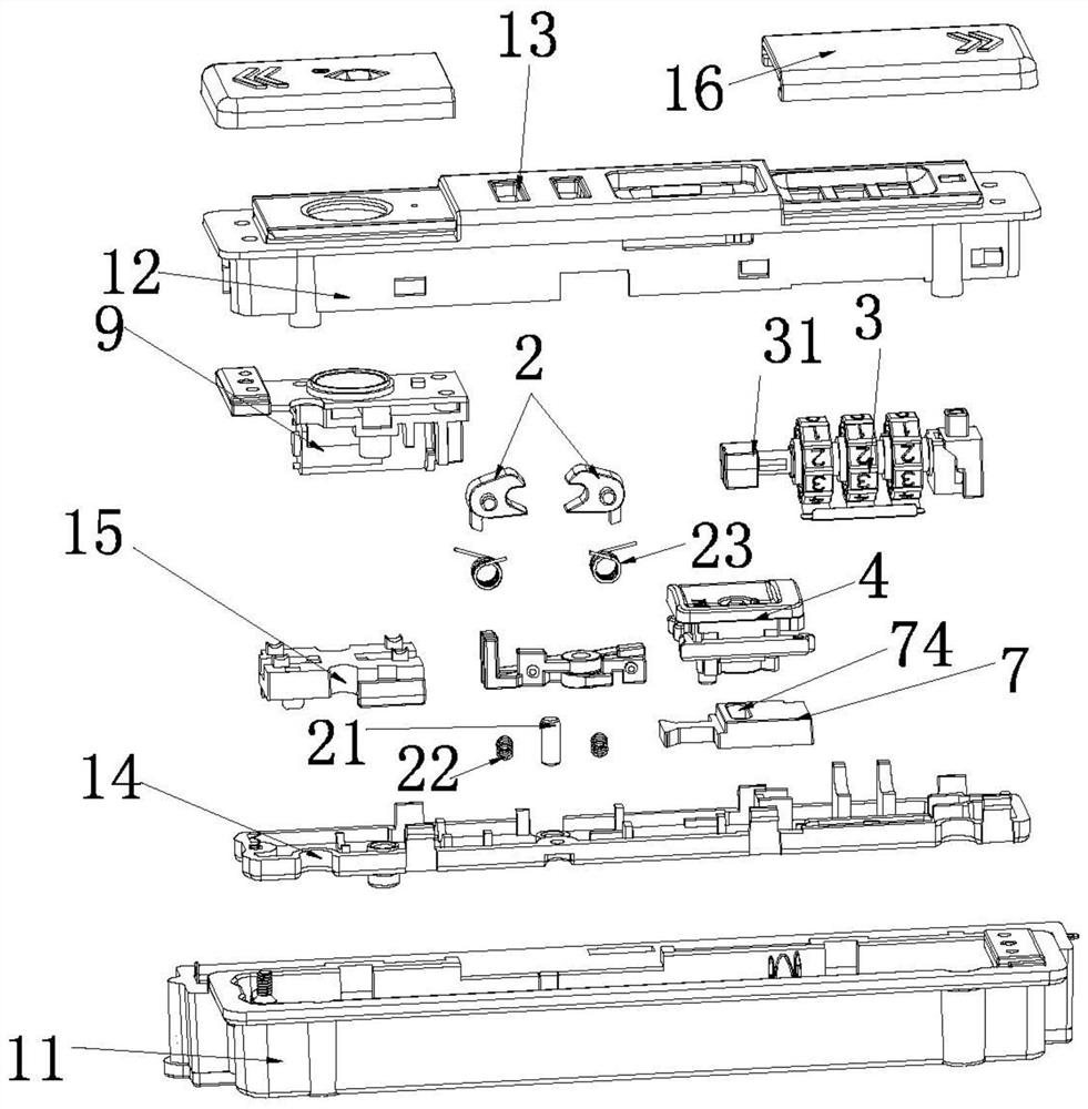
[0039] One of the implementation modes of a kind of zipper combination lock of the present invention, as Figure 1 to Figure 8 As shown, the zipper combination lock includes a lock case, a button assembly 4 , a combination wheel assembly 3 and a power module 5 . The lock case includes a bottom case 11, a face case 12 and a base plate 14 located in the bottom case 11. The bottom case 11 and the face case 12 are detachably connected. way to achieve detachable connection. The front shell 12 is provided with a lock hole 13, and the lock hole 13 is provided with a lock hook 2 which is rotatably installed in the bottom shell 11. In order to realize the anti-theft function, the lock shell is provided with a button for abutting against the lock hook 2 to realize locking. lock block components.

[0040] In this embodiment, in order to make the combination lock more beautiful as a whole and to avoid accidental touches, and to effectively protect the unlocking mechanism from falling fo...

Embodiment 2

[0050] The second embodiment of a kind of zipper combination lock of the present invention, as Figure 9 to Figure 16 As shown, the zipper combination lock includes a lock case, a button assembly 4 , a combination wheel assembly 3 and a power module 5 . The lock case includes a bottom case 11, a face case 12 and a base plate 14 located in the bottom case 11. The bottom case 11 and the face case 12 are detachably connected. way to achieve detachable connection. The front shell 12 is provided with a lock hole 13, and the lock hole 13 is provided with a lock hook 2 which is rotatably installed in the bottom shell 11. In order to realize the anti-theft function, the lock shell is provided with a button for abutting against the lock hook 2 to realize locking. lock block components.

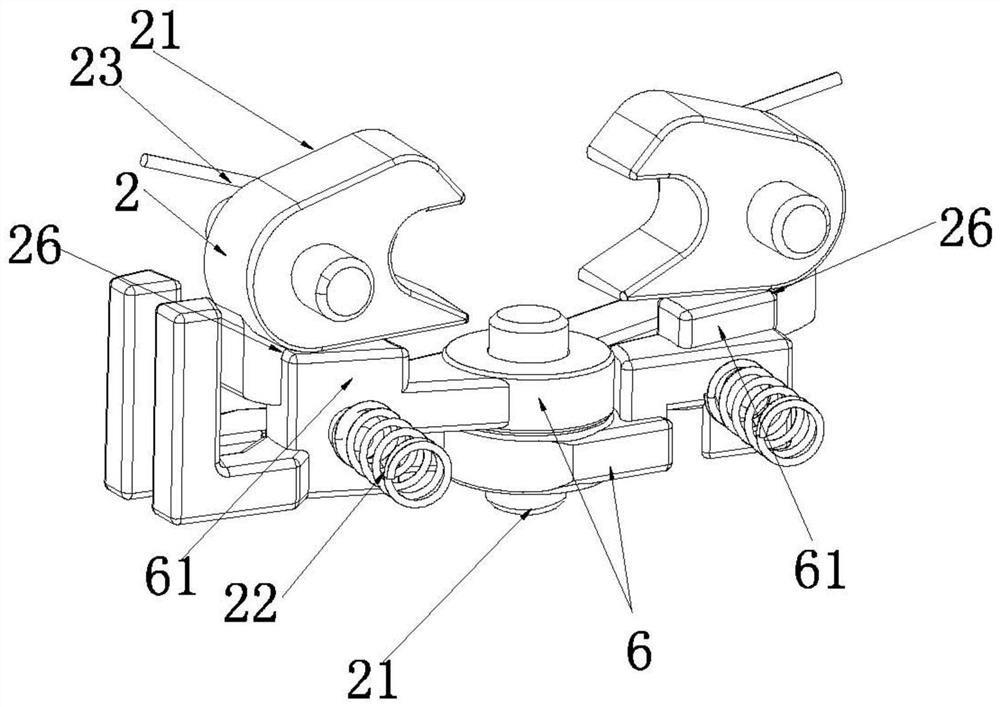
[0051] combine Figure 11 and Figure 12 , the lock hook 2 includes a hook portion 23 and a slot 26, and the hook portion 24 is used to hook the zipper piece. The lock block assembly includes a ro...


PUM


Abstract

The invention relates to the technical field of locks, in particular to a zipper coded lock. The zipper coded lock comprises a lock block assembly used for abutting against a lock hook to achieve locking; the lock block assembly comprises a rotating shaft, two lock block bodies which are arranged in a crossed mode and can rotate around the rotating shaft and an elastic piece driving the two lock block bodies to be folded; and the zipper coded lock further comprises an unlocking mechanism. In the unlocking process, the unlocking mechanism drives the two lock block bodies to be opened so as to release abutting against the lock hook, the lock hook is enabled to rotate, and unlocking is achieved. Locking or unlocking of the lock hook is realized by adopting the two rotatable and crossed lock block bodies, the conventional unlocking mode of horizontal movement of the lock block is replaced by a rotary unlocking mode of the lock block bodies, and the transmission relationship among all partsis optimized, so that the whole transmission process is more compact and smooth, the abrasion of rotary unlocking is smaller, the service life of the zipper coded lock is prolonged, rotary unlockingis more labor-saving than pushing unlocking, and the unlocking is more convenient.

Description

technical field [0001] The invention relates to the technical field of locks, in particular to a zipper combination lock. Background technique [0002] The zipper combination lock is provided with a keyhole, and a hook for locking the zipper sheet is arranged in the keyhole. The zipper combination lock is also provided with a lock block for resisting the lock hook. The lock block can be translated up and down or left and right. When locking, the lock block is against the lock hook, thereby restricting the lock hook from being able to rotate, thereby realizing the locking of the zipper piece. When unlocking, after the lock block is translated, the lock block releases the locking of the lock hook, so that the lock hook Can be rotated to realize unlocking of the zipper piece. [0003] This kind of locking block moves horizontally to unlock the structure, the structure is complex, and the degree of wear is large. After a long time of use, it will cause problems such as difficul...

Claims


Application Information

Patent Timeline
Patent Type & Authority Applications(China)
IPC IPC(8): E05B37/02E05B65/00E05B15/00
CPCE05B37/02E05B65/00E05B15/00
Inventor 赖秀兴郭镜辉吴锋
Owner YIFENG MFG
Learn More