
Textile material tensile strength detection device

A technology for tensile strength and detection devices, applied to measuring devices, using stable tension/pressure to test the strength of materials, analyzing materials, etc., can solve the problems of difficult cloth fixing and insufficient clamping, and improve the safety of detection , prevent fabric damage, simple and convenient operation

Active Publication Date: 2021-02-26
ZHEJIANG MEILAIYA TEXTILE
View PDF5 Cites 3 Cited by
  • Summary
  • Abstract
  • Description
  • Claims
  • Application Information

AI Technical Summary

Problems solved by technology

[0004] Aiming at the deficiencies of the prior art, the present invention provides a textile material tensile strength detection device, which solves the problem of difficulty in fixing the cloth and insufficient clamping

Method used


Image

  • Textile material tensile strength detection device
  • Textile material tensile strength detection device
  • Textile material tensile strength detection device

Examples


Embodiment 1

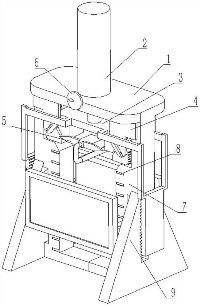
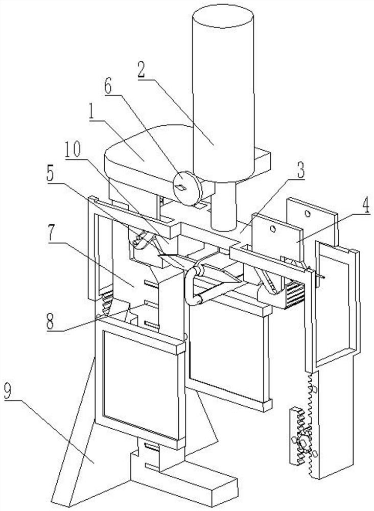
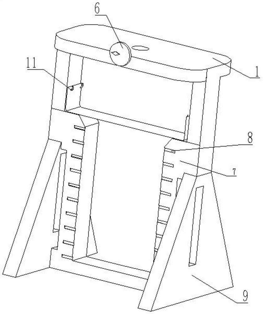
[0031] see Figure 1-7 , a textile material tensile strength detection device, comprising a frame 1, the upper surface of the frame 1 is fixedly connected with a telescopic cylinder 2, the output end of the telescopic cylinder 2 is fixedly connected with a pressing plate 3, and the surface of the pressing plate 3 is provided with a detection mechanism 5 , the surface of the frame 1 is fixedly connected with a display panel 7, the front of the display panel 7 is provided with a scale line 8, the front of the frame 1 is fixedly installed with a pressure gauge 6, and the bottom of the frame 1 is welded with a fixed plate 4, showing The surface of the plate 7 is fixedly connected with a support 9 .

[0032] The inner wall of the frame 1 is fixedly connected with pins 11, the number of pins 11 is provided in two groups, each group has two, and the two groups of pins 11 are all symmetrically distributed with the centerline of the frame 1 as the axis of symmetry; The cloth is direct...

Embodiment 2

[0039] see Figure 8 , on the basis of Embodiment 1, in this embodiment, the protection device 56 includes a rotating gear 561, the surface of the rotating gear 561 is meshed with a right tooth plate 562 and a left tooth plate 563 respectively, and the top of the right tooth plate 562 is fixedly connected to the connection The bottom of the frame 57, the top of the left tooth plate 563 is fixedly connected with a connecting slide bar 564, and the two ends of the connecting slide bar 564 are fixedly connected with a protective frame 565, and the rotating gear 561 meshed with it is driven by the right tooth plate 562 to rotate. The rotation of the rotating gear 561 will drive the movement of the connecting slide bar 564, thereby causing the protective frame 565 to rise from the bottom to improve the overall safety of the entire device.

[0040] The inside of the protective frame 565 is clamped with tempered glass 566, the axis of the rotating gear 561 is rotatably connected to t...


PUM


Abstract

The invention relates to the technical field of textile detection, and discloses a textile material tensile strength detection device. The device comprises a rack, a telescopic cylinder is fixedly connected to the upper surface of the rack, a pressing plate is fixedly connected to the output end of the telescopic cylinder, a detection mechanism is arranged on the surface of the pressing plate, a display panel is fixedly connected to the surface of the rack, scale marks are formed in the front portion of the display panel, a pressure gauge is fixedly installed on the front portion of the rack,and a support is fixedly connected to the surface of the display panel. According to the textile material tensile strength detection device, through downward movement of the telescopic cylinder, a pressing block is firstly driven to move and make contact with the surface of a clamping block, the pressing block moves downwards to push the clamping block to move downwards under the action of an inclined surface so as to compress detected cloth, and meanwhile, a detection pressing rod is driven to move downwards to drive the cloth to be subjected to tensile detection, therefore, clamping and detecting of the cloth are synchronously achieved, and the operation is easy and convenient.

Description

technical field [0001] The invention relates to the technical field of textile testing, in particular to a textile material tensile strength testing device. Background technique [0002] Textile fabrics are divided into two types according to the weaving method: weft-knitted fabrics and warp-knitted fabrics. Weft-knitted fabrics are often made of low-elastic polyester yarn or special-shaped polyester yarn, nylon yarn, cotton yarn, wool yarn, etc. Circle weaves, etc., are woven on various weft knitting machines. [0003] At present, many textile enterprises are in the process of producing textile materials. Some enterprises will perform tensile testing on the materials, and many testing equipments are cumbersome to fix the fabric in use. If the clamping is not in place, it is easy for the testing personnel. Therefore, a textile material tensile strength detection device is proposed to solve the above-mentioned problems. Contents of the invention [0004] Aiming at the de...

Claims


Application Information

Patent Timeline
Patent Type & Authority Applications(China)
IPC IPC(8): G01N3/08G01N3/04
CPCG01N3/08G01N3/04G01N2203/0003G01N2203/0017G01N2203/0075G01N2203/04G01N2203/0605G01N2203/0676G01N2203/0682
Inventor 王楠睿
Owner ZHEJIANG MEILAIYA TEXTILE
Learn More