


Quick Research
Generate reliable direction feasibility study reports for your R&D in just a few steps.

Technical Q&A
Discover and master advanced knowledge NOW. Basics, ideas, possibilities, all at once.

Find Solutions
As an expert in R&D theories, this can generate solutions to your technical problems instantly.

Evaluate Feasibility
Analyze your overall solution with one click, know your potential R&D risks in advance.

Monitor Landscape
Get weekly tech updates, stay abreast of the latest tech innovations and key insights.
Tunnel smoke exhaust device, tunnel and installation method of smoke exhaust valve structure
A technology of smoke exhaust device and installation method, which is applied in mine/tunnel ventilation, tunnels, safety devices, etc., which can solve problems such as failure, tunnel structure and personnel evacuation hazards, insufficient power of smoke exhaust device, etc., to reduce dynamic performance Requirements, the effect of overall structural stability
- Summary
- Abstract
- Description
- Claims
- Application Information
AI Technical Summary
Problems solved by technology
Method used
Image

Examples
Embodiment 1
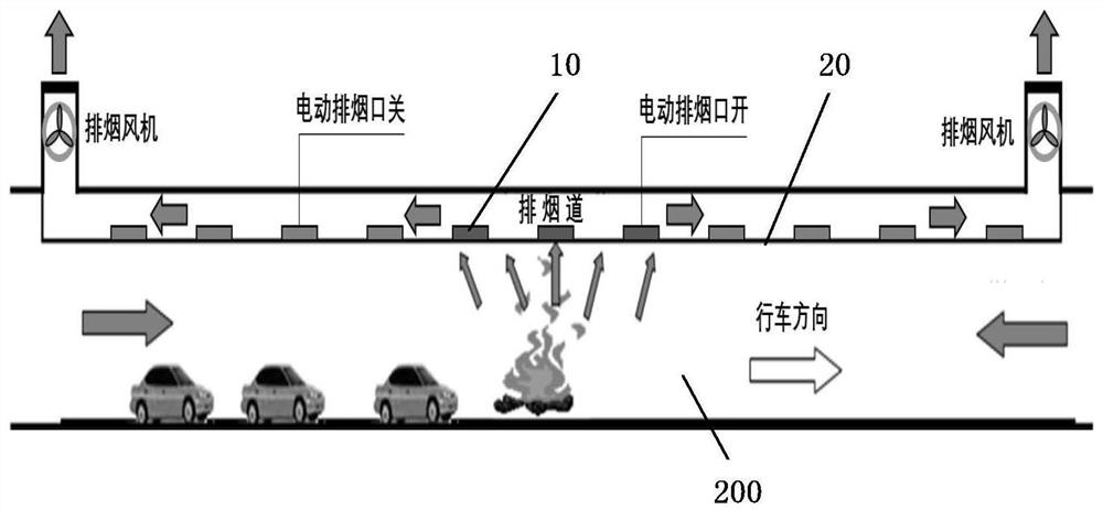
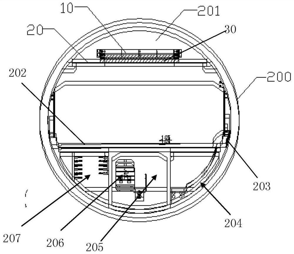
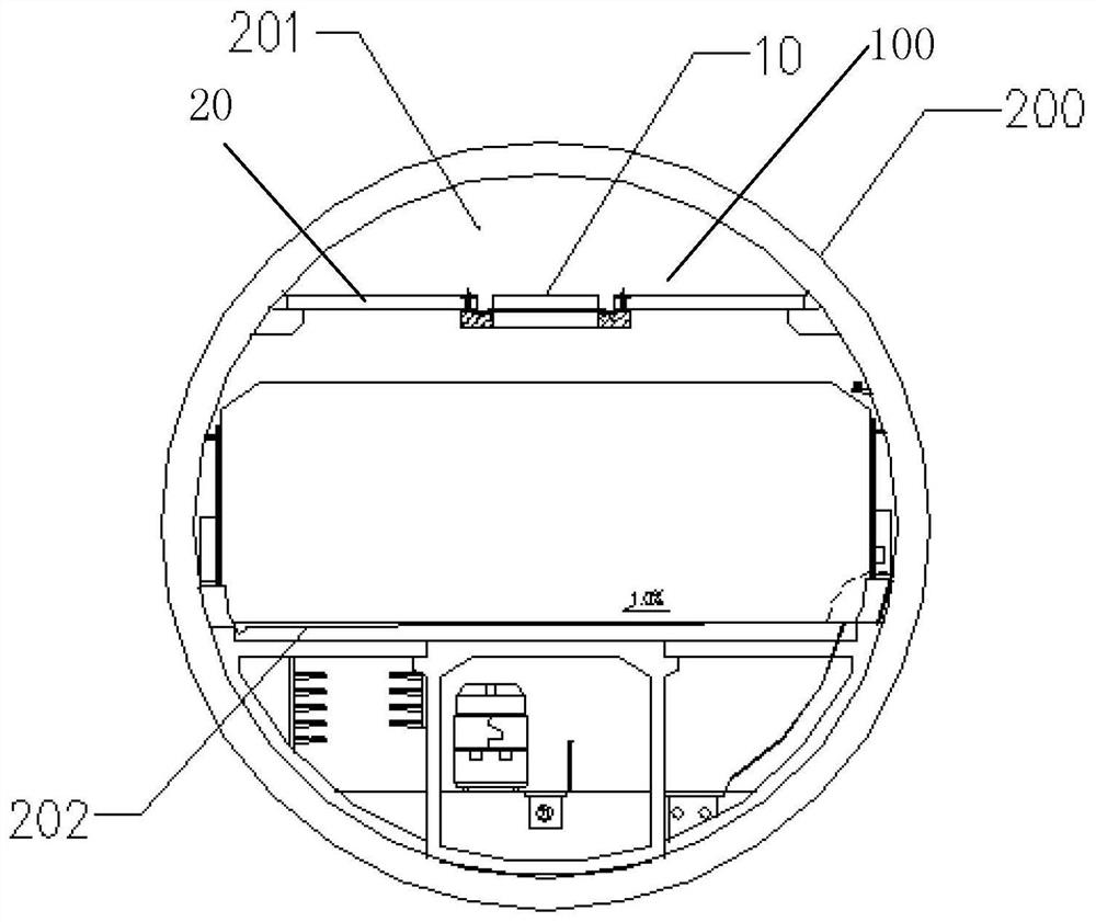
[0037] Such as Figure 1-7 As shown, the present invention provides a tunnel, the tunnel includes a tunnel body 200 and a tunnel smoke exhaust device 100, a smoke exhaust duct 201 is formed between the top of the inner wall of the tunnel body 200 and the flue plate 20, the The tunnel smoke exhaust device is used to exhaust smoke when a fire occurs in the tunnel body 200 .
[0038]The bottom of the tunnel body 200 is provided with a driveway slab 202, and one side of the driveway slab 202 is provided with a plurality of escape covers 203, and a slide room 204 is provided below the escape cover 203, and one side of the slide room 204 A safety passage 205 is provided, and a rescue lane 215 is provided on the side of the safety passage 205 , and a cable passage 207 is provided on the side of the rescue lane 215 .
[0039] The tunnel smoke exhaust device 100 includes at least one smoke exhaust valve structure 10 and a flue plate 20 installed on the top of the tunnel body 200. The ...
Embodiment 2
[0059] Such as Figure 8-10 As shown, embodiment 2 provides a tunnel safety evacuation structure located under the tunnel slab, including an escape cover 203 installed on one side of the driveway slab 202, and the escape cover 203 is located at the driveway evacuation opening on the side of the driveway. The driveway evacuation opening is connected with the slide room / stairwell 204 in the lower side space of the tunnel driveway slab 202, the slide room / stairwell 204 is connected with the evacuation channel 205 under the driveway slab through the fire door 214, the slide room / stairwell 204 is connected with the evacuation There is a residual pressure valve 212 between the channels 203, the evacuation channel 205 is connected with the rescue lane 215 in the lower middle space of the lane plate 202 through the fire door 214, the side of the rescue lane 215 is provided with a cable channel 207, and the two ends of the tunnel are equipped with a tunnel working well 208. The tunnel ...
PUM
 Abstract
Description
Claims
Application Information
 - R&D Engineer
- R&D Manager
- IP Professional
- Industry Leading Data Capabilities
- Powerful AI technology
- Patent DNA Extraction
Browse by: Latest US Patents, China's latest patents, Technical Efficacy Thesaurus, Application Domain, Technology Topic, Popular Technical Reports.
© 2024 PatSnap. All rights reserved.Legal|Privacy policy|Modern Slavery Act Transparency Statement|Sitemap|About US| Contact US: help@patsnap.com