
Vehicle control method and system

A vehicle control and control command technology, which is applied to vehicle components, circuits or fluid pipelines, transportation and packaging, etc., can solve the problem of difficult wiring harness and control unit space layout, cumbersome functional interaction signal interaction, and difficult quality problem management and control, etc. problem, achieve the effect of saving time and labor costs, solving long development cycle, and breaking functional limitations

Active Publication Date: 2021-02-26
DONGFENG MOTOR CORP HUBEI
View PDF6 Cites 2 Cited by
  • Summary
  • Abstract
  • Description
  • Claims
  • Application Information

AI Technical Summary

Problems solved by technology

[0003] In the case of multiple control units, different control units will have different suppliers, so there will be the following problems: For example, in the pre-development stage of the vehicle, it will involve supplier designation, supplier technical exchanges, and the relationship between the control units. Functional interaction and signal interaction are cumbersome, and it takes a long time and a large cost of manpower and material resources to adjust before it can provide the interaction of each control unit in the function control of the vehicle and the interaction of signals between each control unit
Furthermore, due to the functional correlation between different control units, interconnection is required, which eventually leads to difficulties in the spatial layout of wiring harnesses and control units.
[0004] The number of control units on a vehicle ranges from a dozen to as many as 20 to 30. In this case, the cost of development is high, quality control is difficult, and system security risks are relatively high

Method used


Image

  • Vehicle control method and system
  • Vehicle control method and system
  • Vehicle control method and system

Examples


Embodiment Construction

[0047] Embodiments of the present invention will be described in further detail below in conjunction with the accompanying drawings.

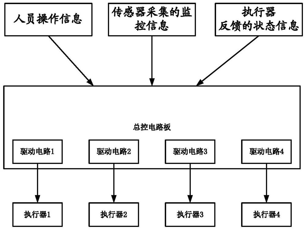
[0048] Embodiments of the present invention provide a vehicle control method and system, which can drive the corresponding actuators by combining the main control circuit board and various actuators corresponding to various functional modules, and driving the corresponding actuators according to the driver's operation. Simplify the layout and wiring of the vehicle, reduce the difficulty of vehicle development, strong portability, low development cost, and shorten the development cycle.

[0049] In order to achieve the above-mentioned technical effects, the general idea of ​​the application is as follows:

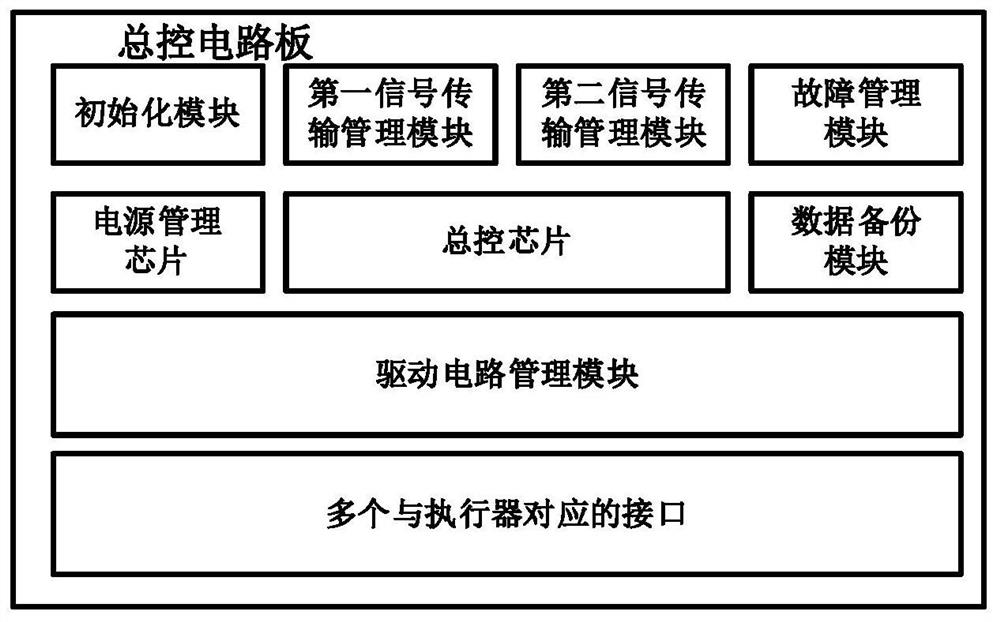
[0050] A vehicle control system, characterized in that it includes a master control circuit board on which a master control chip, sensors and various drive circuits are arranged, and the master control circuit board is physically connected to...


PUM


Abstract

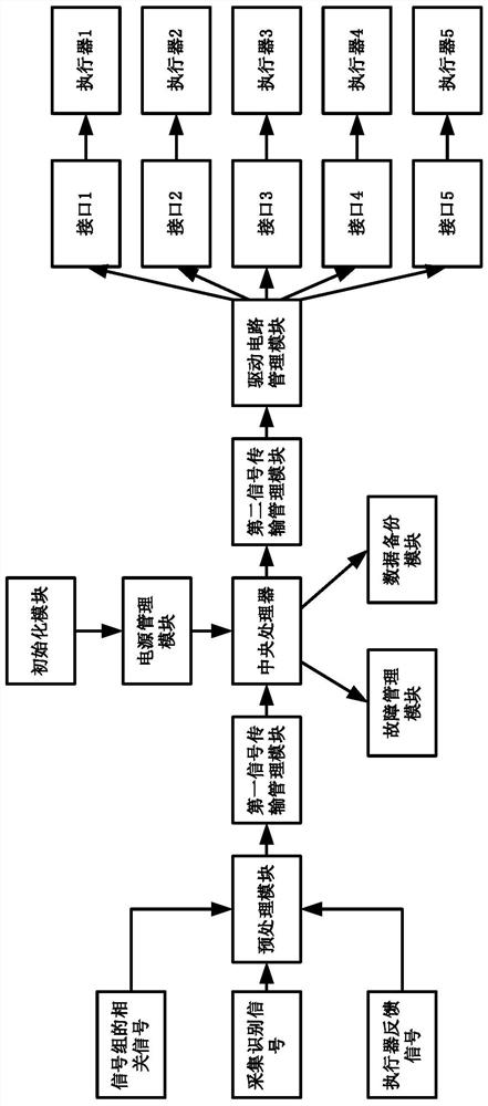
The invention discloses a vehicle control method and system, and relates to the field of vehicle control information processing, the system comprises a general control circuit board, a general controlchip, a sensor and a plurality of driving circuits are arranged on the general control circuit board, and the general control circuit board is physically and directly connected with an actuator through the driving circuits; the general control circuit board is used for directly receiving and analyzing state information fed back by an actuator, monitoring information acquired by a sensor and personnel operation information; the general control chip generates a control command set according to the state information, the monitoring information and the personnel operation information; and the general control circuit board is also used for directly driving the corresponding actuator through the corresponding types of driving circuits according to the control command set. The general control circuit board and various driving circuits of actuators corresponding to various functional modules are integrated into one device, layout and wiring of the whole vehicle can be simplified, the development difficulty of the whole vehicle is reduced, the transportability is high, the development cost is low, and the development period is shortened.

Description

technical field [0001] The invention relates to the field of vehicle control information processing, in particular to a vehicle control method and system. Background technique [0002] At present, the control units on the car are independent of each other. They are connected and communicated through the vehicle wiring harness, and the control of the whole vehicle is completed through the cooperation between the controllers. At the same time, a single control only controls a certain aspect of the function; for example The engine controller mainly controls the work of the engine, while the steering controller mainly controls the work of the steering gear. [0003] In the case of multiple control units, different control units will have different suppliers, so there will be the following problems: For example, in the pre-development stage of the vehicle, it will involve supplier designation, supplier technical exchanges, and the relationship between the control units. Function...

Claims


Application Information

Patent Timeline
Patent Type & Authority Applications(China)
IPC IPC(8): B60R16/023
CPCB60R16/0231
Inventor 郝慧兵
Owner DONGFENG MOTOR CORP HUBEI
Learn More