Edge chamfering device for wooden building blocks
A chamfering device and edge technology, which is applied to the field of edge chamfering devices for wooden building blocks, can solve the problems of complicated operation, low efficiency, time-consuming and labor-intensive, etc., and achieve the effect of simple and convenient operation.
- Summary
- Abstract
- Description
- Claims
- Application Information
AI Technical Summary
Problems solved by technology
Method used
Image

Examples
Embodiment 1
[0067] A wooden building block edge chamfering device, such as figure 1 with figure 2As shown, it includes bed 1, geared motor 2 and chamfering assembly 3, geared motor 2 is installed on the front right side of the top of bed 1, chamfering assembly 3 is installed on the top of bed 1, chamfering assembly 3 and geared motor 2 output shaft connection.
[0068] Manual grinding is time-consuming, cumbersome and inefficient. This equipment can automatically chamfer the edge of building blocks, saving time and effort, simple operation and high efficiency. The motor 2 and the output shaft of the reduction motor 2 rotate to make the chamfering assembly 3 run. At the same time, people manually make the building blocks move to the right in the chamfering assembly 3. The chamfering assembly 3 chamfers the edges of the building blocks, and then the polished building blocks are Gravity falls from the chamfering component 3 to the right side of the top of the bed 1. If people still need t...
Embodiment 2
[0070] On the basis of Example 1, such as figure 2 , image 3 with Figure 4 As shown, the chamfering assembly 3 includes a support frame 31, a limit plate 32, a first rotating shaft 33, a saw blade 34, a second rotating shaft 35, a first bevel gear set 36, a third rotating shaft 37, and a second bevel gear set 38 , the fourth rotating shaft 39 and the third bevel gear set 310, the top of the bed 1 is provided with four support frames 31, the top of the four support frames 31 is connected to the limit plate 32, and the output shaft of the reduction motor 2 is provided with the first rotating shaft 33 , the upper middle part of the limiting plate 32 is rotatably provided with a second rotating shaft 35, the upper part of the first rotating shaft 33 is provided with a first bevel gear set 36, the first bevel gear set 36 is connected to the front of the second rotating shaft 35, and the top of the bed 1 A third rotating shaft 37 is provided on the rear side of the right side, ...
Embodiment 3
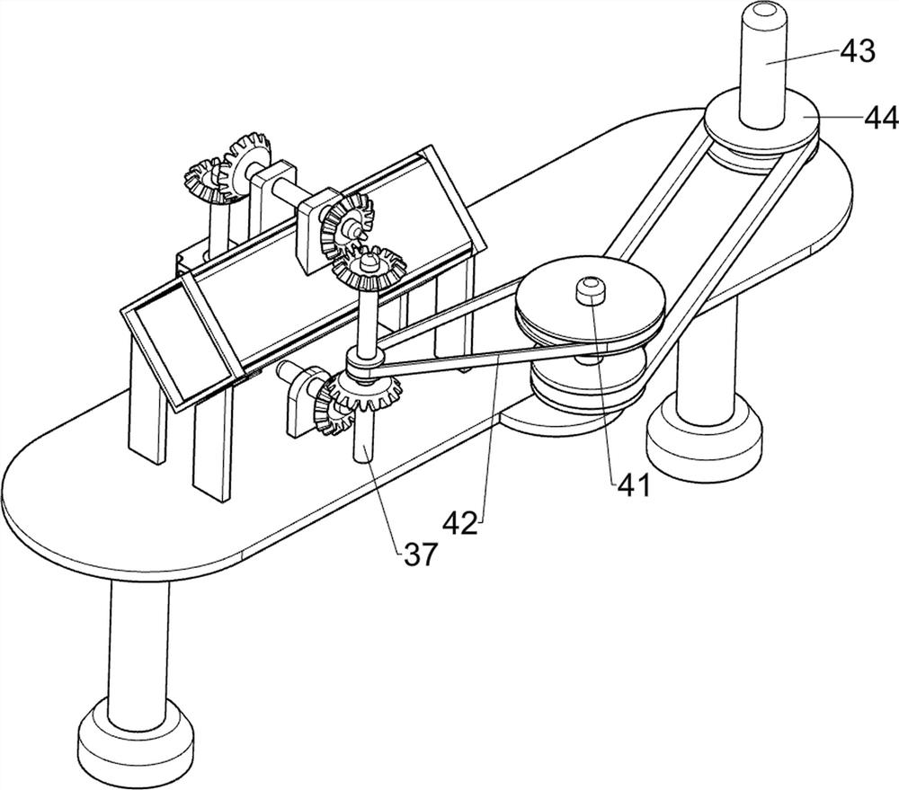
[0073] On the basis of Example 2, such as figure 1 , Figure 4 , Figure 5 , Image 6 with Figure 7 As shown, a transmission assembly 4 is also included, the top of the bed 1 is provided with a transmission assembly 4, the transmission assembly 4 is connected to the third rotating shaft 37, and the transmission assembly 4 includes a fifth rotating shaft 41, a first transmission device 42, and a sixth rotating shaft 43 and the second transmission device 44, the top rear side of the bed 1 is rotatably provided with a fifth rotating shaft 41, and the first transmission device 42 is connected between the upper part of the fifth rotating shaft 41 and the third rotating shaft 37, and the top of the bed 1 rotates on the left side The formula is provided with a sixth rotating shaft 43, and a second transmission device 44 is connected between the lower part of the fifth rotating shaft 41 and the lower part of the sixth rotating shaft 43.
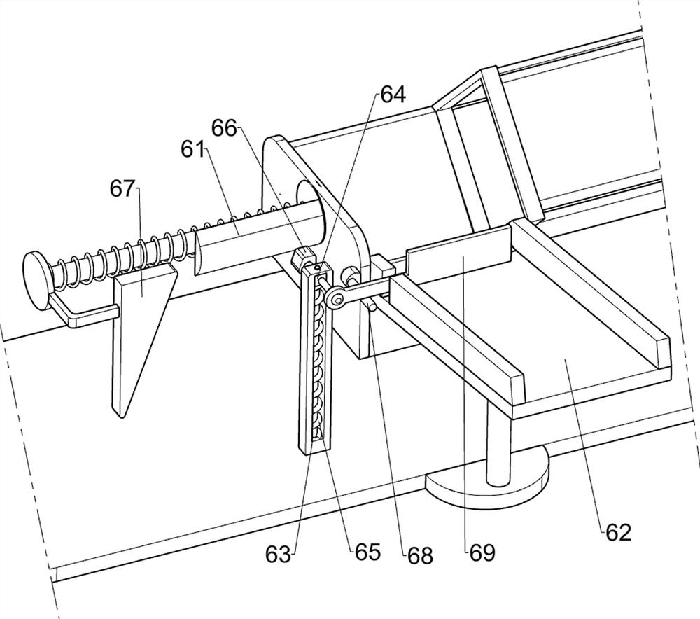
[0074] Also includes a feeding assembly 5...
PUM
 Abstract
Description
Claims
Application Information
 - R&D
- Intellectual Property
- Life Sciences
- Materials
- Tech Scout
- Unparalleled Data Quality
- Higher Quality Content
- 60% Fewer Hallucinations
Browse by: Latest US Patents, China's latest patents, Technical Efficacy Thesaurus, Application Domain, Technology Topic, Popular Technical Reports.
© 2025 PatSnap. All rights reserved.Legal|Privacy policy|Modern Slavery Act Transparency Statement|Sitemap|About US| Contact US: help@patsnap.com