Automatic horizontal milling machine

A milling machine, horizontal technology, applied in the field of automatic horizontal milling machines, can solve the problems of difficult and stable control of the moving speed of the worktable, affecting the processing efficiency, easy to damage the milling cutter, etc., to reduce the phenomenon of knife punching, ensure milling efficiency, and save electricity. Effect

Active Publication Date: 2021-02-26
千叶金属制品(深圳)有限公司
View PDF9 Cites 4 Cited by
  • Summary
  • Abstract
  • Description
  • Claims
  • Application Information

AI Technical Summary

Problems solved by technology

[0003] In view of the above-mentioned related technologies, the inventor believes that when a conventional milling machine mills the surface of a workpiece, it usually manually moves the workbench along the horizontal direction, and the workpiece is clamped on the workbench, so that the milling cutter moves from the workpiece to the surface. One end of the workpiece is milled to the other. Due to the way of manual feeding, it is difficult for novices to control the movement speed of the worktable smoothly. If the movement is too fast, the milling cutter will be easily damaged, and if the movement is too slow, it will affect the processing efficiency.

Method used


Image

  • Automatic horizontal milling machine
  • Automatic horizontal milling machine
  • Automatic horizontal milling machine

Examples


Embodiment Construction

[0030] The following is attached Figure 1-3 The application is described in further detail.

[0031] The embodiment of the present application discloses an automatic horizontal milling machine.

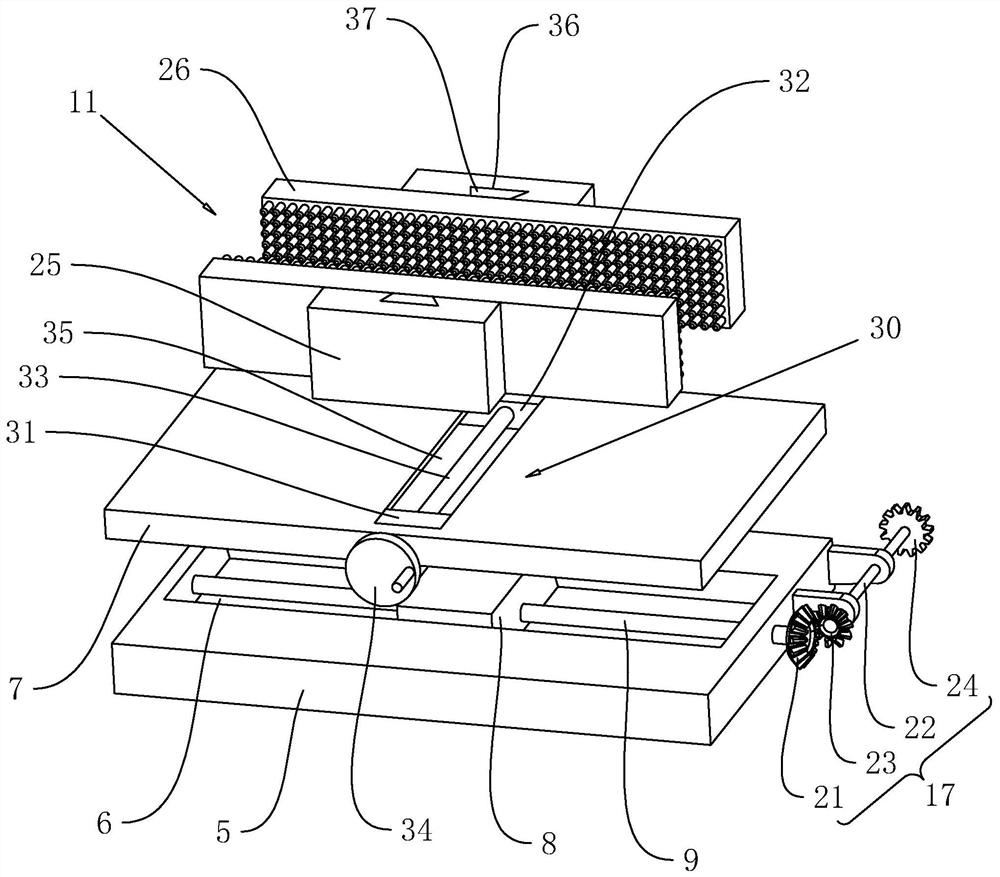
[0032] refer to figure 1 , an automatic horizontal milling machine, including a base 1, a back plate 2 is fixed on the upper surface of the base 1 by welding, a servo motor 3 is arranged on the upper end of the back plate 2, and the servo motor 3 is fixed on the back plate 2 by bolts On the side wall of the back plate 2, the rotating shaft of the servo motor 3 is coaxially fixed with a milling cutter 4, and the side wall of the back plate 2 is fixed with a timing switch 41, and the timing switch 41 is electrically connected to the electric circuit of the servo motor 3.

[0033] refer to figure 1 , the top of the base 1 is provided with a mounting table 5, the mounting table 5 is located on the side of the back plate 2 away from the servo motor 3, the mounting table 5 is located belo...


PUM


Abstract

The invention relates to an automatic horizontal milling machine. The automatic horizontal milling machine comprises a base, wherein a back plate is fixed to the upper surface of the base; a servo motor is fixed to the side wall of the back plate; a milling cutter is coaxially fixed to a rotating shaft of the servo motor; a mounting table is arranged above the base and located below the milling cutter; a first sliding groove is formed in the upper surface of the mounting table; a workbench slides above the mounting table in the length direction of the base; a first sliding block is fixed to the bottom face of the workbench and slides in the first sliding groove; a first lead screw is arranged in the first sliding groove in a rotating mode; the first sliding block is connected to the firstlead screw in a threaded mode. a first driving piece used for driving the first lead screw and the rotating shaft of the servo motor to rotate synchronously is arranged at the end, extending out of the mounting table, of the first lead screw; a clamping assembly used for clamping a workpiece is arranged above the workbench; and an adjusting piece used for adjusting the height of the mounting tableis arranged below the mounting table. The automatic horizontal milling machine has the effects that the milling efficiency is guaranteed, and the cutter beating phenomenon is reduced.

Description

technical field [0001] The present application relates to the technical field of milling machines, in particular to an automatic horizontal milling machine. Background technique [0002] A milling machine is a machine tool with a wide range of uses. It can process planes (horizontal planes, vertical planes), grooves (key slots, T-shaped slots, dovetail slots, etc.), toothed parts (gears, spline shafts, sprockets), Spiral surface (thread, spiral groove) and various curved surfaces. In addition, it can also be used to process the surface and inner hole of the rotating body and perform cutting work. When the milling machine is working, the workpiece is installed on the worktable or the accessories such as the indexing head. The main movement of the milling cutter is the rotation, supplemented by the feed movement of the worktable or the milling head, and the workpiece can obtain the required processing surface. [0003] In view of the above-mentioned related technologies, the...

Claims


Application Information

Patent Timeline
Patent Type & Authority Applications(China)
IPC IPC(8): B23C1/027B23C9/00B23Q3/06B23Q5/28
CPCB23C1/027B23C9/00B23Q3/06B23Q5/28Y02P70/10
Inventor 李明光苏永智雷成龙邓维绍
Owner 千叶金属制品(深圳)有限公司
Why Eureka
Try Eureka