Distributing system and method for flue gas desulfurization and denitrification activated carbon

A technology of desulfurization and denitrification and distribution system, which is applied in the field of flue gas desulfurization and denitrification activated carbon distribution system and distribution, and flue gas treatment equipment. It can solve the problems of waste, fluctuation of flue gas volume and pollutant difficulty, and unscientific problems, so as to reduce operating costs , the movement speed is reduced, and the effect of reducing loss

Active Publication Date: 2022-05-03
ZHONGYE-CHANGTIAN INT ENG CO LTD +1
View PDF9 Cites 0 Cited by
  • Summary
  • Abstract
  • Description
  • Claims
  • Application Information

AI Technical Summary

Problems solved by technology

However, since the original flue gas volume and the concentration of pollutants in the flue gas are different for each project, and the flue gas volume and the difficulty of pollutants often fluctuate, it is not scientific to set the activated carbon circulation volume of the system according to the maximum demand. , resulting in a great waste of

Method used


Image

  • Distributing system and method for flue gas desulfurization and denitrification activated carbon
  • Distributing system and method for flue gas desulfurization and denitrification activated carbon
  • Distributing system and method for flue gas desulfurization and denitrification activated carbon

Examples


Embodiment 1

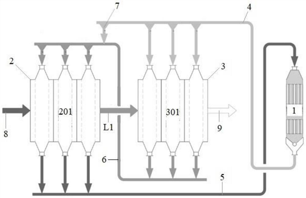
[0082] Such as figure 1 As shown, an activated carbon distributing system for flue gas desulfurization and denitration, the system includes a desorption tower 1, a desulfurization tower 2, and a denitration tower 3. According to the direction of the flue gas, the raw flue gas inlet pipe 8 is connected with the air inlet of the desulfurization tower 2 . The exhaust port of the desulfurization tower 2 is connected with the air inlet port of the denitrification tower 3 through the first pipeline L1. The exhaust port of the denitrification tower 3 is connected with the clean flue gas exhaust pipe 9 . The discharge port of the desorption tower 1 is connected with the feed port of the denitrification tower 3 through the first activated carbon conveying device 4 . The discharge port of the desulfurization tower 2 is connected with the feed port of the desorption tower 1 through the second activated carbon conveying device 5 . The discharge port of the denitrification tower 3 is co...

Embodiment 2

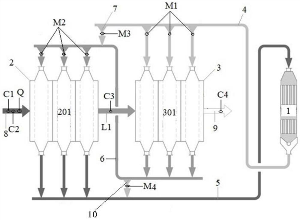
[0084] Example 1 is repeated, except that a second bypass activated carbon delivery device 10 is provided upstream of the third activated carbon delivery device 6 , and the second bypass activated carbon delivery device 10 is connected to the second activated carbon delivery device 5 .

Embodiment 3

[0086] Repeat Example 2, except that the desulfurization tower 2 is provided with three desulfurization units 201 .


PUM


Abstract

The invention discloses a flue gas desulfurization and denitrification activated carbon distribution system, which comprises an analysis tower, a desulfurization tower and a denitration tower. The raw flue gas is desulfurized and denitrified through the desulfurization tower and denitrification tower in turn. The discharge port of the analysis tower is connected with the feed port of the denitrification tower through the first activated carbon conveying device. The discharge port of the desulfurization tower is connected with the feed port of the desorption tower through the second activated carbon conveying device. The discharge port of the denitrification tower is connected with the feed port of the desulfurization tower through the third activated carbon conveying device. The first activated carbon conveying device is led from the first bypass activated carbon conveying device to be connected to the third activated carbon conveying device or to the feed port of the desulfurization tower. The invention realizes independent and precise control of the active carbon circulation volume of the desulfurization tower and the denitrification tower, reduces the loss of active carbon, and reduces the operating cost and dust emission concentration.

Description

technical field [0001] The invention relates to flue gas treatment equipment technology, in particular to a flue gas desulfurization and denitrification activated carbon distributing system and a distributing method, belonging to the technical field of flue gas purification. Background technique [0002] In iron and steel plants, many flue gas purification adopts two-stage activated carbon flue gas purification process: the flue gas process is that the flue gas passes through the first-level adsorption tower (the main function is desulfurization) and the second-level adsorption tower (the main function is denitrification), and then flows from the chimney Discharge; the process of activated carbon is: the activated carbon after analysis is transported to the secondary adsorption tower by the feeding conveyor of the secondary tower, and after the activated carbon absorbs some pollutants, it is sent to the primary adsorption tower by the conveyor of the primary tower to absorb t...

Claims


Application Information

Patent Timeline
Patent Type & Authority Patents(China)
IPC IPC(8): B01D53/04
CPCB01D53/04B01D2259/40088B01D2257/302B01D2257/40B01D2258/0283
Inventor 李勇刘昌齐邓增军傅旭明
Owner ZHONGYE-CHANGTIAN INT ENG CO LTD
Why Eureka
Try Eureka