A river purification device for ecological energy saving and environmental protection
A technology of energy saving, environmental protection, purification device, applied in chemical instruments and methods, separation methods, filtration and separation, etc., can solve the problems of large-scale purification equipment occupying a large area, unable to adapt to purification conditions, and poor filter bearing capacity, etc. Filtration effect and high stability, low cost of use, impact reduction effect
- Summary
- Abstract
- Description
- Claims
- Application Information
AI Technical Summary
Problems solved by technology
Method used
Image
Examples
Embodiment 1
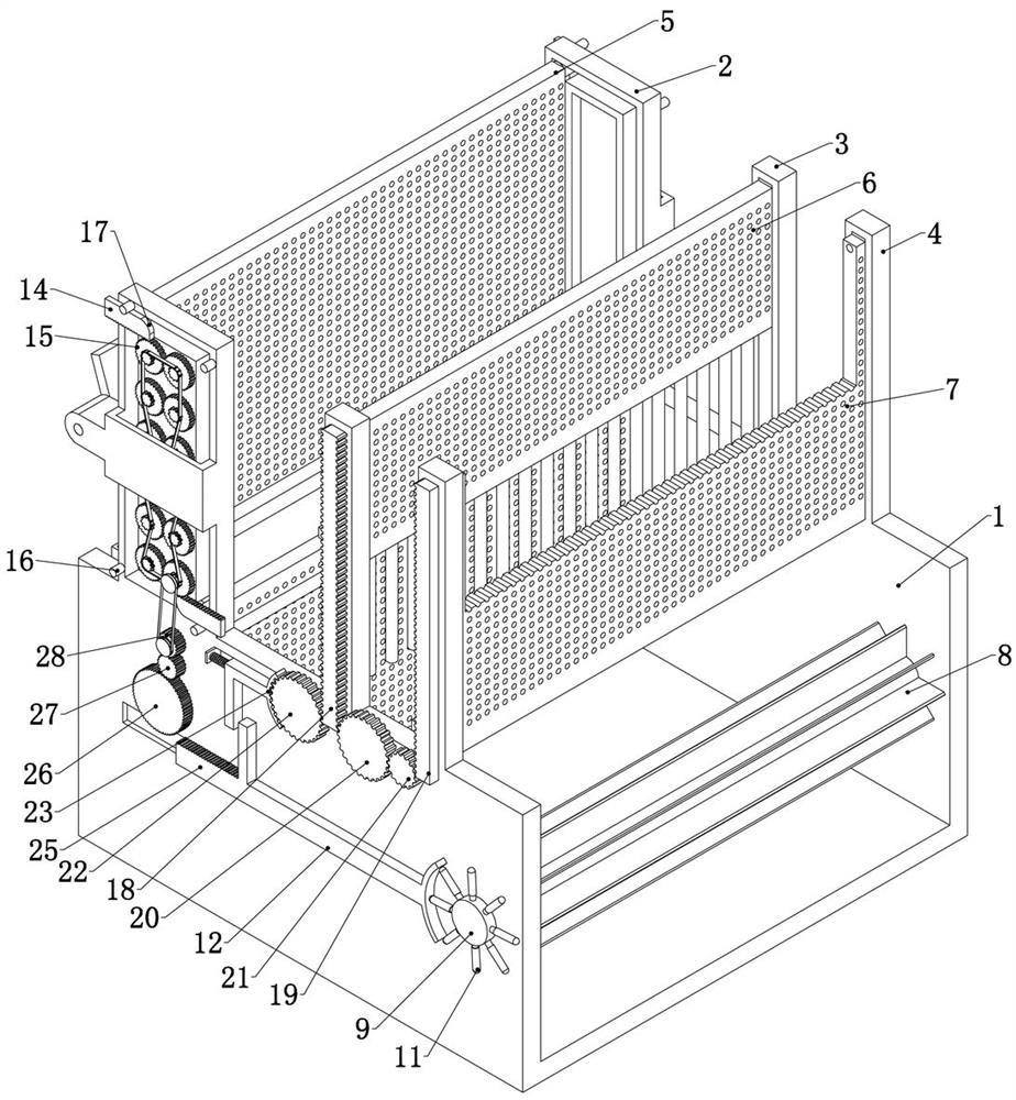
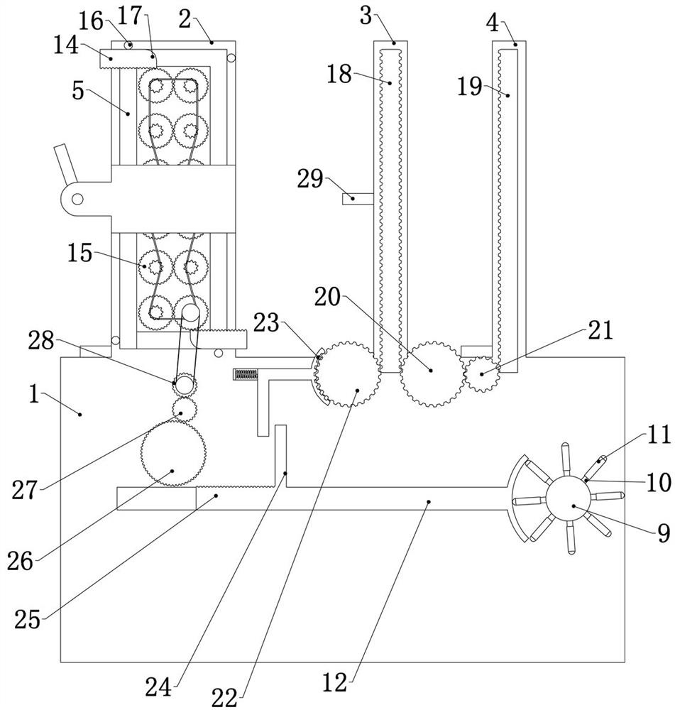
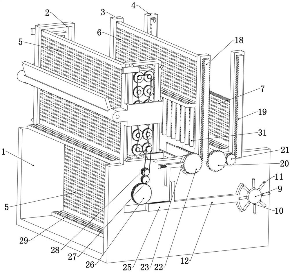
[0038] Embodiment 1, the present invention is a river purification device for ecological energy saving and environmental protection, which is characterized in that it includes a U-shaped main body 1, refer to figure 1 , image 3 , the section of the main body 1 is a square groove shape, including the bottom surface placed on the river bed and the side walls fixedly connected on both sides of the bottom surface and attached to the inner side wall of the river bank. When in use, the main body 1 of the device is placed in Hanoi, the said The two side walls of the main body 1 are fixedly connected with an annular front slide rail 2, the front slide rail 2 is a square ring, and two front filter screens 5 are slidably connected in the front slide rail 2, specifically, the two The upper side walls of the front filter screen 5 are all rotatably connected with a front slide shaft 13 that is slidably connected in the front slide rail 2, and the front slide rail 13 is slidably connected ...
Embodiment 2
[0043] Embodiment two, on the basis of embodiment one, refer to Figure 7 , the two front sliding shafts 13 are fixedly connected with a front rack 14, the movement of the front rack 14 can drive the front sliding shaft 13 to move synchronously, thereby driving the front filter screen 5 to move;
[0044] The side wall of the front slide rail 2 is rotatably connected with a number of front gears 15 capable of meshing with the front rack 14, and a number of front gears 15 are connected through a chain transmission structure. Specifically, a number of front gears 15 are fixedly connected coaxially There are sprockets, and several sprockets are connected by chains. In order to ensure the stability of long-distance chain transmission, the side wall of the front slide rail 2 can be rotated to connect the tensioning pulley, and the chain can be bypassed and tensioned while connecting all the sprockets. wheel, so that several front gears 15 can rotate in the same direction synchronous...
Embodiment 3
[0049] Embodiment three, on the basis of embodiment one, refer to figure 2 One side of the middle filter screen 6 is fixedly connected with a middle rack 18, the movement of the middle rack 18 can drive the middle filter screen 6 to move synchronously, and one side of the rear filter screen 7 is fixedly connected with a rear rack 19, and the rear The movement of the rack 19 can drive the rear filter screen 7 to move synchronously. One side of the middle rack 18 is meshed with a rear large gear 20 that is rotatably connected to the side wall of the main body 1, and the side of the rear large gear 20 is meshed with a rotatably connected The rear pinion 21 on the side wall of the main body 1, the rear pinion 21 meshes with the rear rack 19, the transmission ratio of the rear large gear 20 and the rear pinion 21 is 2:1, this setting can Make the middle rack 18 keep the movement process of the rear rack 19 twice as long as the movement process of the middle rack 18 during the fall...
PUM
 Abstract
Description
Claims
Application Information
 - R&D
- Intellectual Property
- Life Sciences
- Materials
- Tech Scout
- Unparalleled Data Quality
- Higher Quality Content
- 60% Fewer Hallucinations
Browse by: Latest US Patents, China's latest patents, Technical Efficacy Thesaurus, Application Domain, Technology Topic, Popular Technical Reports.
© 2025 PatSnap. All rights reserved.Legal|Privacy policy|Modern Slavery Act Transparency Statement|Sitemap|About US| Contact US: help@patsnap.com


