A push-down type cream cake molding device
A cake and cream technology, applied in baking, food science, baked food processing, etc., can solve the problems of inconsistent cake quality and slow production speed
- Summary
- Abstract
- Description
- Claims
- Application Information
AI Technical Summary
Problems solved by technology
Method used
Image
Examples
Embodiment 1
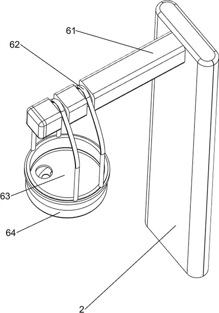
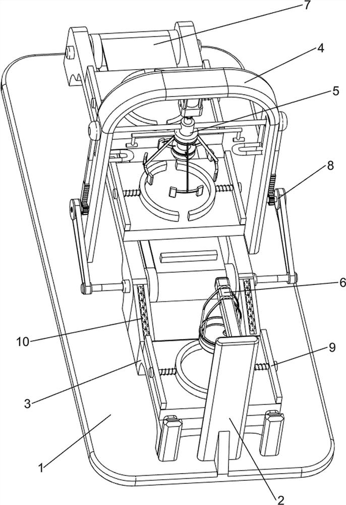
[0068] A push-down type cream cake molding device, such as figure 1 As shown, it includes a bottom plate 1, a support column 2, a first workbench 3, a mounting frame 4, a pressing mechanism 5 and a screening mechanism 6. The upper front part of the bottom plate 1 is provided with a support column 2, and the upper front part of the bottom plate 1 is provided with a first A workbench 3, the support column 2 is located in front of the first workbench 3, the bottom plate 1 is provided with a mounting frame 4 in the upper middle, the inner top of the mounting frame 4 is provided with a pressing mechanism 5, and the upper rear side of the support column 2 is provided with a screening mechanism 6, The screening mechanism 6 is located above the first workbench 3 .
[0069] When making cakes, pastry chefs cannot efficiently complete the production of large batches of cakes. The present invention helps people to quickly complete the decoration of cakes. First, place the round cream cake...
Embodiment 2
[0071] On the basis of Example 1, as figure 2 and image 3As shown, the pressing mechanism 5 includes a cylinder 51, a push rod 52, a sliding rod 53, a first spring 54, an approach block 55, a stopper 56, a clamp 57 and a forming scraper 58, and a cylinder 51 is installed on the top of the mounting frame 4 The bottom of the cylinder 51 is connected with a push rod 52, the upper part of the push rod 52 is provided with a sliding rod 53, the left and right sides of the sliding rod 53 are slidably connected with the mounting frame 4, and the left and right sides of the bottom of the sliding rod 53 are connected with a first spring 54. The bottom of a spring 54 is connected to the mounting frame 4 , the middle of the push rod 52 is slidably connected to a proximity block 55 , and the left and right sides of the inner middle of the mounting frame 4 are provided with stoppers 56 . Four clamps 57 are uniformly rotated on the lower side. The inner side of the clamps 57 is rotatably ...
Embodiment 3
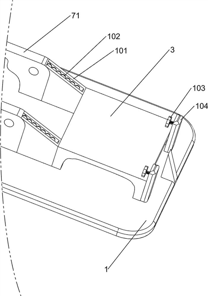
[0076] On the basis of Example 2, as figure 1 , Figure 4 , Figure 5 , Image 6 and Figure 7 As shown, it also includes a feeding mechanism 7. The upper and middle part of the bottom plate 1 is provided with a feeding mechanism 7. The feeding mechanism 7 includes a mounting block 71, a rotating shaft 72, a pulley 73, a conveyor belt 74 and a second workbench 75. There are mounting blocks 71 on the sides, and the front and rear parts of the mounting block 71 are both rotatably connected with rotating shafts 72. The two rotating shafts 72 are both provided with pulleys 73, and a conveyor belt 74 is wound around the two pulleys 73. The conveyor belt 74 is placed There is a second workbench 75 , and the second workbench 75 is slidably connected with the mounting block 71 .
[0077] First, place the cake on the second table 75, push the conveyor belt 74, rotate the conveyor belt 74 through the rotation of the rotating shaft 72 and the pulley 73, and the conveyor belt 74 makes...
PUM
 Abstract
Description
Claims
Application Information
 - R&D Engineer
- R&D Manager
- IP Professional
- Industry Leading Data Capabilities
- Powerful AI technology
- Patent DNA Extraction
Browse by: Latest US Patents, China's latest patents, Technical Efficacy Thesaurus, Application Domain, Technology Topic, Popular Technical Reports.
© 2024 PatSnap. All rights reserved.Legal|Privacy policy|Modern Slavery Act Transparency Statement|Sitemap|About US| Contact US: help@patsnap.com


