


Quick Research
Generate reliable direction feasibility study reports for your R&D in just a few steps.

Technical Q&A
Discover and master advanced knowledge NOW. Basics, ideas, possibilities, all at once.

Find Solutions
As an expert in R&D theories, this can generate solutions to your technical problems instantly.

Evaluate Feasibility
Analyze your overall solution with one click, know your potential R&D risks in advance.

Monitor Landscape
Get weekly tech updates, stay abreast of the latest tech innovations and key insights.
Motor assembly machine and method
A technology for motor units and fuselages, applied in the direction of electromechanical devices, electric components, manufacturing motor generators, etc., can solve problems such as inability to locate and assemble the main shaft
- Summary
- Abstract
- Description
- Claims
- Application Information
AI Technical Summary
Problems solved by technology
Method used
Image

Examples
specific Embodiment approach 1
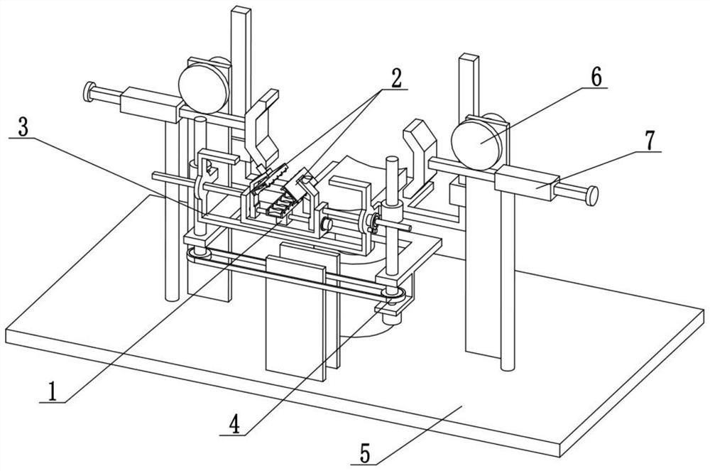
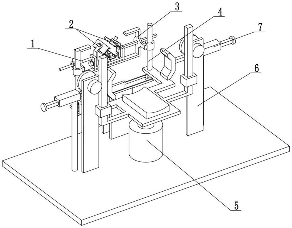
[0031] Combine below Figure 1-9 Describe this embodiment. The present invention relates to the technical field of motor assembly, more specifically, a motor assembly machine, including a spindle erecting mechanism 1, a spindle conveying mechanism 2, a horizontal fine-tuning mechanism 3, a vertical fine-tuning mechanism 4, and a fuselage positioning mechanism 5 , the clamping linkage mechanism 6 and the fuselage clamping mechanism 7, the two fuselage clamping mechanisms 7 are connected to the fuselage positioning mechanism 5, and the two clamping linkage mechanisms 6 are connected to the fuselage positioning mechanism 5 Above, the two clamping linkage mechanisms 6 are engaged with the two fuselage clamping mechanisms 7 respectively for transmission, and the two clamping linkage mechanisms 6 are both engaged with the fuselage positioning mechanism 5 for transmission, and the vertical fine-tuning mechanism 4 is connected to the fuselage positioning mechanism 5 Above, the horizon...
specific Embodiment approach 2
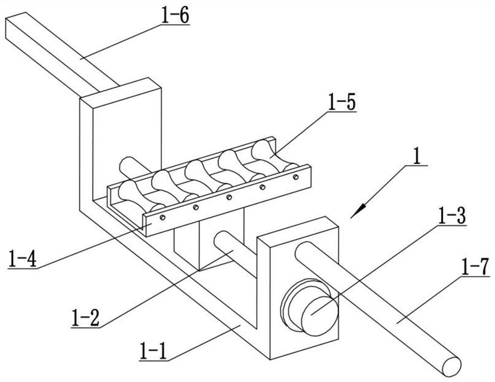
[0034] Combine below Figure 1-9 Describe this embodiment, this embodiment will further explain the first embodiment, the main shaft erecting mechanism 1 includes a load-bearing beam 1-1, a horizontal screw rod 1-2, a horizontal motor 1-3, a support frame 1-4, and a pulley 1 -5. The rectangular sliding rod 1-6 and the push-pull screw rod 1-7, the push-pull screw rod 1-7 is fixedly connected to the right end of the load-bearing beam 1-1, and the left end of the load-bearing beam 1-1 is fixedly connected to the rectangular slide rod 1-6, horizontal The screw rod 1-2 is rotatably connected to the load-bearing beam 1-1, the horizontal screw rod 1-2 is fixedly connected to the output shaft of the horizontal motor 1-3, and the horizontal motor 1-3 is fixedly connected to the load-bearing beam 1-1, supporting The frame 1-4 is threadedly connected on the horizontal screw rod 1-2, and a plurality of pulleys 1-5 are all rotatably connected on the support frame 1-4.
specific Embodiment approach 3
[0036] Combine below Figure 1-9 Describe this embodiment, this embodiment will further explain the second embodiment, the main shaft conveying mechanism 2 includes a moving arm 2-1, a cylinder 2-2, a hanging plate 2-3, a conveying wheel 2-4 and a conveying motor 2 -5, a plurality of conveying wheels 2-4 are all rotatably connected to the hanging plate 2-3, the hanging plate 2-3 is fixedly connected to the output shaft of the cylinder 2-2, and the cylinder 2-2 is fixedly connected to the moving arm 2-1 Above, the two moving arms 2-1 are all screwed on the horizontal screw rod 1-2, and the multiple conveying wheels 2-4 are fixedly connected with the conveying motor 2-5.
[0037] Place the motor spindle on a plurality of pulleys 1-5, and then use the horizontal motor 1-3 to drive the horizontal screw rod 1-2 to rotate, so that the horizontal screw rod 1-2 drives the two moving arms 2-1 on the load-bearing beam 1-1 Sliding up and approaching, respectively drive the cylinder 2-2 ...
PUM
 Abstract
Description
Claims
Application Information
 - R&D Engineer
- R&D Manager
- IP Professional
- Industry Leading Data Capabilities
- Powerful AI technology
- Patent DNA Extraction
Browse by: Latest US Patents, China's latest patents, Technical Efficacy Thesaurus, Application Domain, Technology Topic, Popular Technical Reports.
© 2024 PatSnap. All rights reserved.Legal|Privacy policy|Modern Slavery Act Transparency Statement|Sitemap|About US| Contact US: help@patsnap.com